Throttleable swirling injector for combustion chambers

a swirling injector and combustion chamber technology, applied in the direction of burners, combustion processes, lighting and heating apparatus, etc., can solve problems such as combustion instability, and achieve the effects of reducing the change in the linear flow rate of fuel, wide throttling range, and further flexibility

Inactive Publication Date: 2007-02-08
AEROJET GENERAL CORP
View PDF12 Cites 14 Cited by
  • Summary
  • Abstract
  • Description
  • Claims
  • Application Information

AI Technical Summary

Benefits of technology

[0008] The present invention resides in a throttling injector that achieves thrust variation by spinning the liquid fuel around the internal wall of a swirl chamber, causing the liquid to be ejected from the chamber around the rim of an orifice in the chamber wall, with thrust variation being achieved by varying the volume of liquid entering the swirl chamber and thereby varying the depth of the layer of the peripheral liquid stream at the outlet orifice rim. The liquid stream that is ejected from the swirl chamber through the outlet orifice will thus occupy only a small fraction of the outlet orifice area at low volumetric flow rates or a majority of, and possibly the entire, outlet orifice area at higher flow rates, and various levels in between. The volumetric flow of liquid fuel that is fed through inlet orifices to the swirl chamber can be varied by continuous changes in the flow rate through an inlet line or through a series of inlet lines that feed the liquid to the chamber, or by stepwise changes produced by opening and closing different numbers of liquid fuel inlets to the swirl chamber. Variation can also be achieved by using inlets of different sizes, or by changes in the manner in which the liquid fuel is directed to individual inlets. All of these variations can be made without any substantial change in the linear velocity of liquid through the outlet orifice, and without any substantial change in the pressure drop, if any, across the orifice. Throttling of the combustion engine by decreasing the volumetric flow of fuel from the injector can thus be achieved without exposing any moving parts to hot combustion gases, and without any need for injecting gas or additives to the fuel or for maintaining a foam or dispersion of any kind in the fuel. A wide throttling range can be achieved by constructing the swirl chamber with a large number of inlets, and further flexibility can be achieved by using inlets of different sizes. Chugging can thus be avoided by reducing changes in the linear flow rate of fuel through the outlet orifice of the injector and thereby minimizing the reduction in pressure drop across the outlet orifice.

Problems solved by technology

When throttling is performed at very high ratios or at very rapid rates, the rapid changes of pressure and the transmission of these changes throughout the system produce a combustion instability in the form of a series of low-pressure fluctuations known as “chugging.”

Method used


Image

  • Throttleable swirling injector for combustion chambers
  • Throttleable swirling injector for combustion chambers
  • Throttleable swirling injector for combustion chambers

Examples


Embodiment Construction

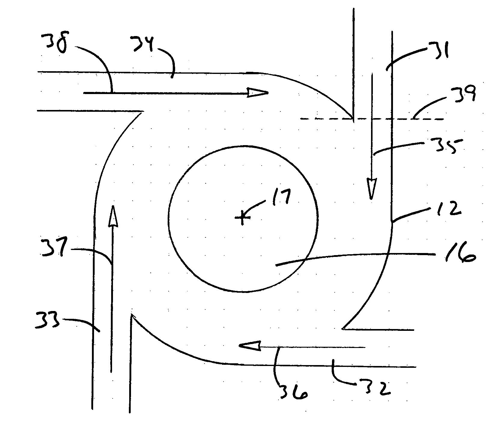
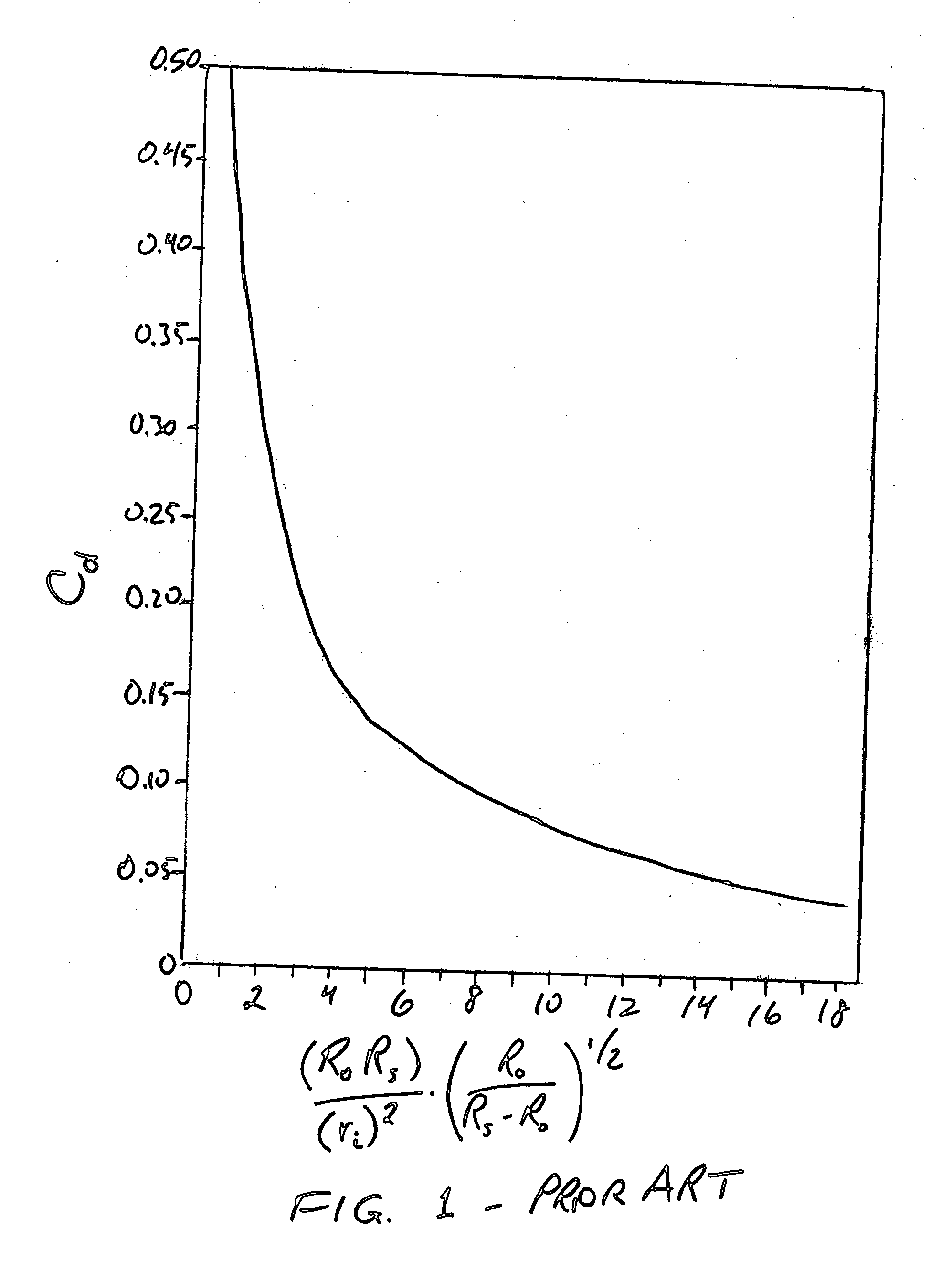
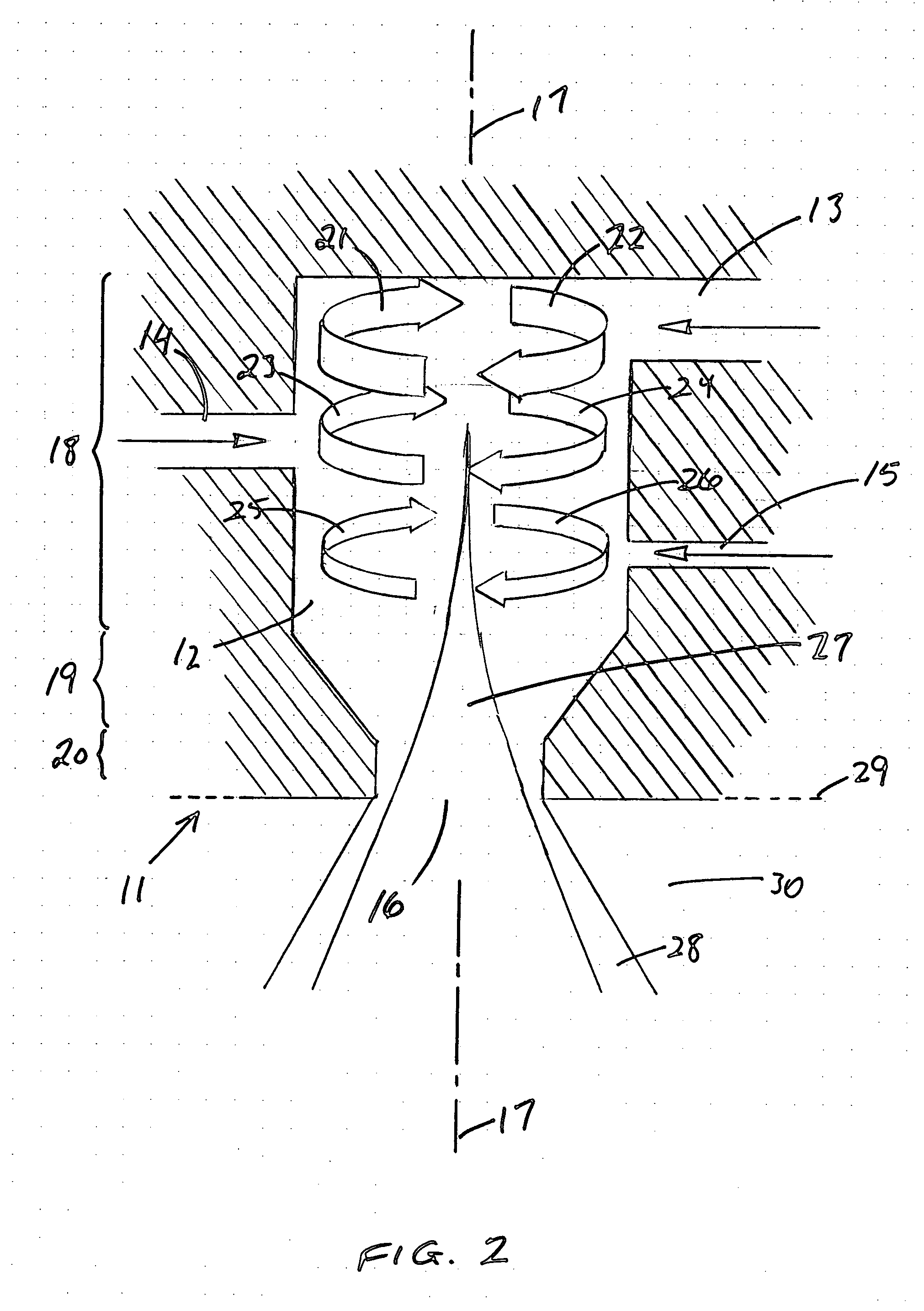
[0018] The swirl chamber is a flow-through receptacle, preferably a body of revolution around a longitudinal axis, that receives an incoming liquid steam and causes the liquid to circulate within the chamber in a swirling motion around the axis to form a vortex of the liquid before the liquid leaves the chamber. The outlet orifice is thus preferably circular, and preferably has a width or diameter that is smaller than other internal portions of the chamber so that diameter of the swirling path of the liquid decreases as the liquid approaches the outlet orifice. The outlet orifice can have the same diameter as the swirl chamber itself, although in preferred embodiments of the invention, the diameter ratio of the widest section of the chamber to the outlet orifice is about 2:1 or greater, or more preferably about 3:1 to about 6:1. This decrease in diameter increases the dispersion angle of the fuel ejected through the outlet orifice into the combustion chamber or engine, forming a str...


PUM


Abstract

A throttling injector is constructed with a swirl chamber, a plurality of tangentially directed liquid fuel inlets and an outlet orifice, the inlets arranged to create a swirling flow in the swirl chamber to leave through the outlet in a stream that is in the shape of a hollow tube or cone. Variations in the number of inlets that are actuated results in variations in the thickness of the wall of liquid in the tube or cone and hence variations in the volumetric flow rate of fuel ejected from the outlet orifice without changing the linear velocity of the fuel in the axial direction through the orifice or the pressure drop across the orifice. The injector thus permits throttling to occur from a high to a low volumetric fuel flow rate without the chugging instability that plagues liquid-fuel-fed combustion chambers of the prior art.

Description

BACKGROUND OF THE INVENTION [0001] 1. Field of the Invention [0002] This invention resides in the field of liquid-fuel combustion engines, and particularly the fuel injectors for such engines. [0003] 2. Description of the Prior Art [0004] Combustion engines powered by liquid fuel are used in a variety of applications. Examples are gas turbines, pre-burners, liquid-propellant rocket motors, and descent engines of space shuttles. In many of these applications, a controlled shutdown, typically involving throttling the engine in a gradual or stepwise manner, is critical to the successful operation of the engine. In thrust-producing engines, a thrust ratio of 30:1 or greater is needed upon shutdown. When throttling is performed at very high ratios or at very rapid rates, the rapid changes of pressure and the transmission of these changes throughout the system produce a combustion instability in the form of a series of low-pressure fluctuations known as “chugging.”[0005] Attempts in the p...

Claims


Application Information

Patent Timeline
Patent Type & Authority Applications(United States)
IPC IPC(8): B05B1/34
CPCB05B1/3426F23R3/28F23D11/383F23D11/04
Inventor HEWITT, ROSS A.
Owner AEROJET GENERAL CORP
Why Eureka
Try Eureka