
Computer power supply and cable

a technology for computers and power supplies, applied in the field of power supplies, can solve the problems of reducing increasing the length of wires and/or cables, and reducing the electrical packing density of electrical devices, so as to reduce the length of wires and/or cables, and reduce the number of loose wires and/or cables

Inactive Publication Date: 2007-02-08
KIM JINSEOK
View PDF3 Cites 2 Cited by
  • Summary
  • Abstract
  • Description
  • Claims
  • Application Information

AI Technical Summary

Benefits of technology

[0006] One objective of the present invention is to reduce the emitted noise from a power supply apparatus when a cooling fan is running. Another objective of the present invention is to reduce wire or cable clutter within a computer housing.
[0010] One objective of the present invention is to reduce wire and / or cable clutter within an electrical housing. Another objective of the present invention is to reduce the length of wires and / or cables and to reduce the number of loose wires and / or cables within the electrical device housing. Still another objective is to centrally locate power within a computer at one or more distribution points to reduce wire and / or cable clutter when connecting to a plurality of electrical components. Yet another objective is to increase airflow over electrical components within a computer housing through reducing wire and / or cable clutter.

Problems solved by technology

These related art power supplies have disadvantages.
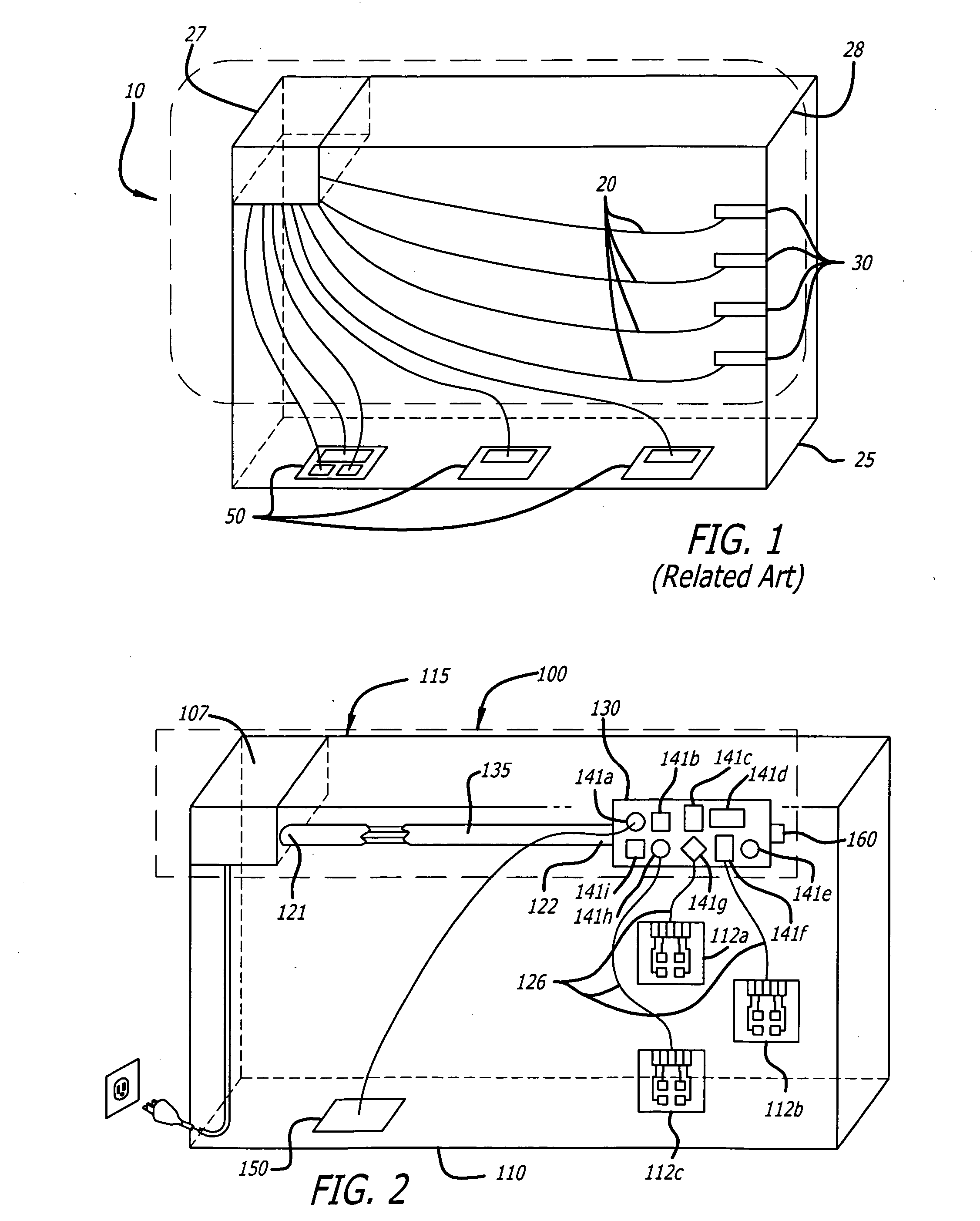
For example, the related art power supply 10 reduces the available volume for inserting electrical components, which results in increased clutter and decreased electrical packing density within the electrical device housing 25.
Furthermore, conventional cooling fans may not properly circulate air to cool electronic components, such as electrical components 30 and 50, that are within an electrical device housing 25 due to clutter created by long wires 20.
In addition, noise emitted by conventional cooling fans may be higher due to higher rotational speed needed because of decreased heat dissipation resulting from wire clutter.

Method used


Image

  • Computer power supply and cable
  • Computer power supply and cable
  • Computer power supply and cable

Examples


Embodiment Construction

[0020] The present invention relates to a computer power supply. More particularly, the invention relates to a computer power supply having improved properties and reduced size requirements.

[0021] Although the invention is illustrated with respect to a computer power supply, it is contemplated that the invention may be utilized wherever there is a desire for efficiently compacting a power supply used for any electrical power housing, while minimizing a volume occupied by the power supply. Reference will now be made in detail to the preferred embodiments of the present invention, examples of which are illustrated in the accompanying drawings.

[0022] Referring to FIG. 2, a power supply apparatus 100 provides power to electrical components, for example circuit cards 112a, 112b and 112c, inside of a computer housing 110. A power supply module 107 converts electrical power, such as incoming electrical power, to at least one power level. In one example, the power supply 107 converts an a...


PUM


Abstract

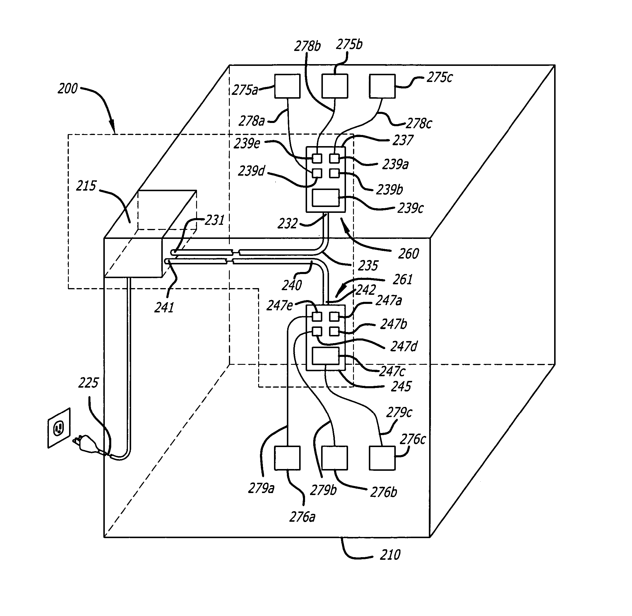
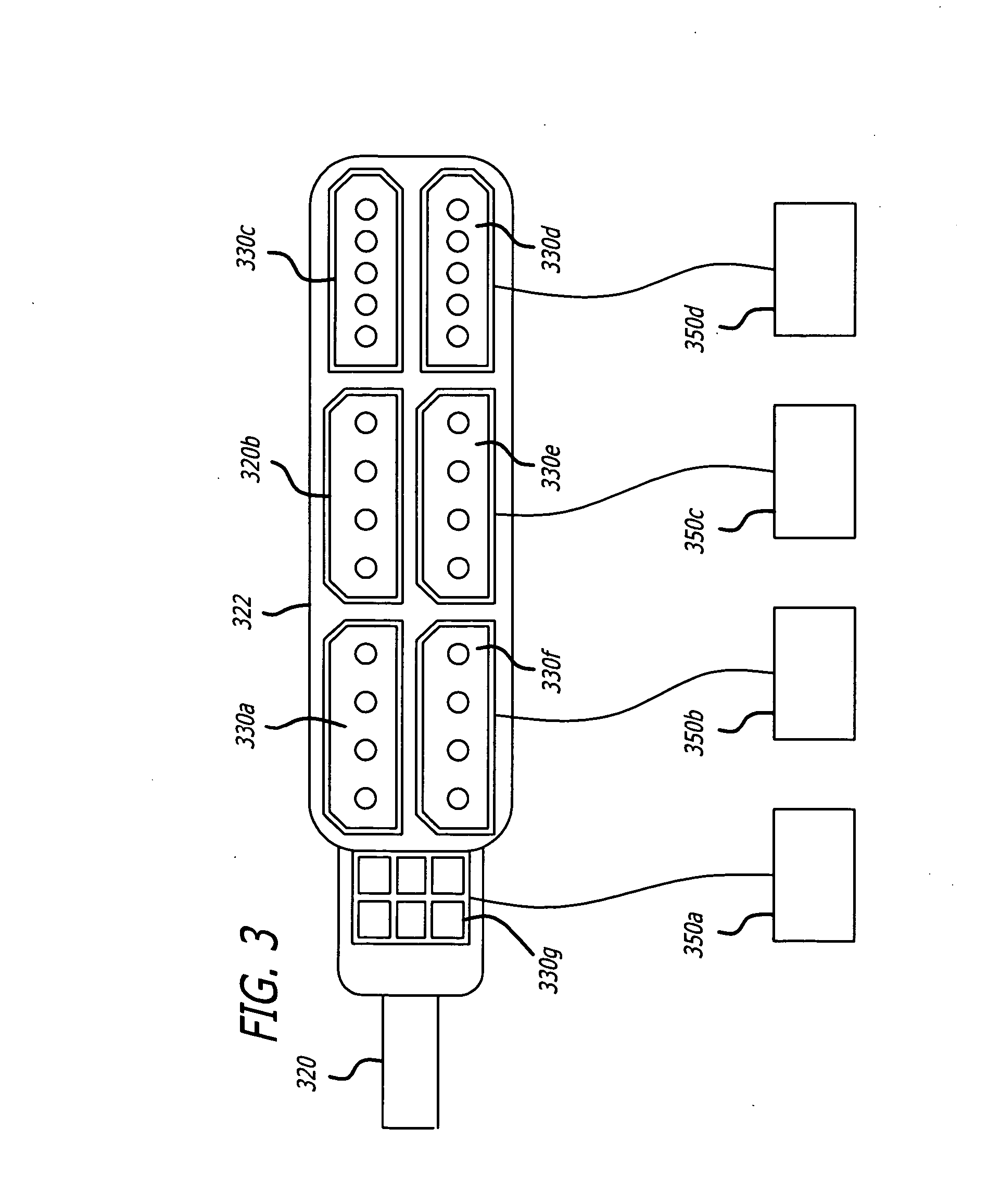
A power supply apparatus is disclosed to provide power to a plurality of electrical components inside a computer housing. The power supply apparatus comprises a power supply module to convert electrical power to at least one power level. At least one power distribution panel is disposed within the computer housing. At least one wiring harness is electrically coupled at a first end of the at least one wiring harness to the at least one power distribution panel. The at least one wiring harness at a second end connects to the power supply module to transfer the at least one power level to the at least one power distribution panel. The at least one power distribution panel provides electrical adapters to transfer the at least one power level to cables that are coupled between the electrical adaptors and the plurality of electrical components.

Description

FIELD OF THE INVENTION [0001] The present invention relates to a power supply. More particularly, the invention relates to a method and apparatus for distributing power from a computer power supply to connect to electronic components within the computer in order to reduce wire and / or cable clutter. BACKGROUND OF THE INVENTION [0002] Related art power supplies are large and occupy large amounts of space within an electrical device housing. FIG. 1 illustrates a related art power supply within an electrical device housing. [0003] As shown, a related art power supply 10 occupies a large amount of area within an electrical device housing 25, such as a desktop or laptop computer. These related art power supplies have disadvantages. For example, the related art power supply 10 reduces the available volume for inserting electrical components, which results in increased clutter and decreased electrical packing density within the electrical device housing 25. In yet another example, the relat...

Claims


Application Information

Patent Timeline
IPC IPC(8): H05K1/02
CPCG06F1/20G06F1/189
Inventor KIM, JINSEOK
Owner KIM JINSEOK
Learn More