Non-feedback type load current controller

a load current controller and non-feedback technology, applied in the direction of instruments, heat measurement, digital computer details, etc., can solve the problems of excessive stress applied to the opening/closing element, abnormality sign cannot be detected, electric load operating in an unintentional state, etc., to achieve enhanced safety

Inactive Publication Date: 2007-02-08
MITSUBISHI ELECTRIC CORP
View PDF11 Cites 147 Cited by
  • Summary
  • Abstract
  • Description
  • Claims
  • Application Information

AI Technical Summary

Benefits of technology

[0013] The present invention has been implemented to solve the problem described above, and has an object to provide a non-feedback type load current controller that can detect a semi-breaking state or semi-short-circuiting state of a power supply circuit to judge the presence or absence of an abnormality sign, and inform abnormality if there is any abnormality sign, whereby maintenance and check can be promoted before a serious accident occurs, and the safety can be enhanced.
[0014] Furthermore, the present invention has also an object to provide a non-feedback type load current controller in which when an abnormality sign state is left unchecked and thus the abnormality state falls into a more risky state, the state is judged as an appearing abnormality state and the driving of the load is stopped to thereby enhance the safety.
[0018] However, the circuit construction is designed so that the current detecting resistor and the electrical load are disconnected by the opening / closing element, and the load current at the time point when the opening / closing element is closed flows in the current detecting resistor while no commutating load current flows in the commutating circuit when the opening / closing element is opened (i.e., sets the open circuit condition), and the measurement voltage achieves the average value of the load current by the smoothening capacitor.
[0019] Accordingly, according to the non-feedback type load current controller of the present invention having the circuit construction described above, with respect to occurrence of a short-circuit accident of an electrical load or a high-level short-circuit accident due to the mixed touch between a negative-side wire and a positive-side power supply line, the current detecting resistor takes a role of a limiting resistor for a transit period until the opening / closing element is urgently interrupted, so that an excessively large stress applied to the opening / closing element can be reduced.

Problems solved by technology

Furthermore, subtle time control is needed to inversely operate the opening / closing element for only a short time without affecting the operation state of the electrical load and check abnormality in the close circuit period or open circuit period of the opening / closing element, and thus there is a risk that the electrical load erroneously operates in an unintentional state.
Accordingly, if the resistance of the electric load does not vary over a level at which the correction based on the feedback control is difficult, an abnormality state cannot be detected, and thus any abnormality sign cannot be detected.
Furthermore, when the connection point between the opening / closing element and the electrical load is grounded to a ground circuit due to mixed touch, the stress applied to the opening / closing element would be excessively increased even if the opening / closing element is urgently interrupted because the current detecting resistor does not function as a current limiting resistor for the opening / closing element.
Therefore, there is a risk that the opening / closing element is damaged.

Method used


Image

  • Non-feedback type load current controller
  • Non-feedback type load current controller
  • Non-feedback type load current controller

Examples


first embodiment

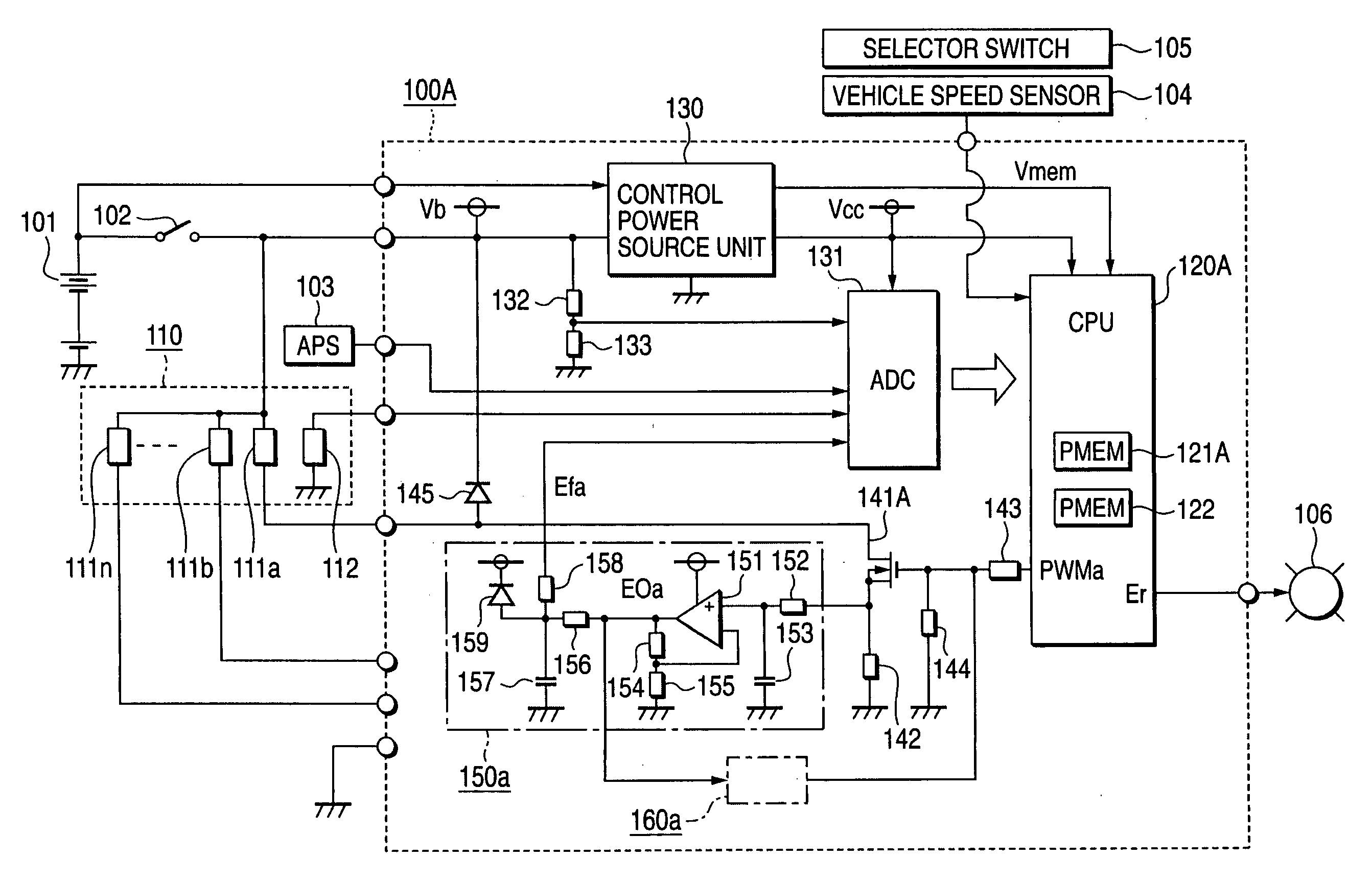
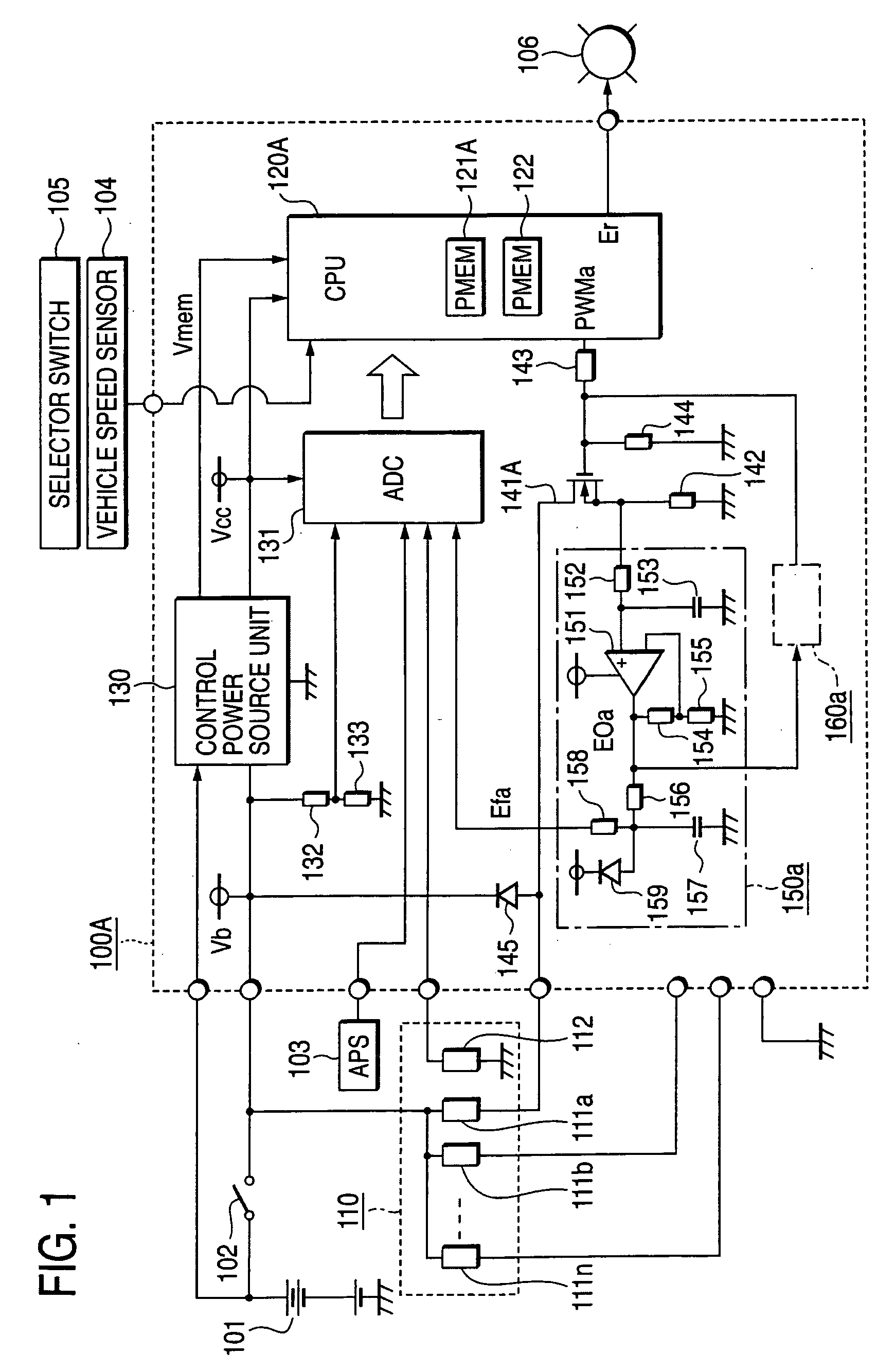
[0031]FIG. 1 is a block diagram showing the construction of a non-feedback type load current controller according to a first embodiment of the present invention.

[0032] In FIG. 1, reference numeral 100A represents a non-feedback type load current controller according to the first embodiment, and the non-feedback type load current controller 100A constitutes a controller for an automatic transmission for a vehicle, for example. Power is supplied from a driving power source 101 as an in-vehicle mount battery through a power supply switch 102 such as a key switch or the like.

[0033] The non-feedback type load current controller 100A is supplied with signals from an accelerator position sensor (APS) 103 for detecting the tread degree of an accelerator pedal (not shown), a vehicle speed sensor 104, a selector switch 105 for detecting the selected position of a selector lever, a temperature sensor (for example, oil temperature sensor) 112 for detecting the temperature of lubricating oil o...

second embodiment

[0140]FIG. 5 shows the construction of a non-feedback type load current controller according to a second embodiment of the present invention.

[0141] In FIG. 5, reference numeral 100B represents the non-feedback type load current controller according to the second embodiment, and as in the case of the first embodiment, the non-feedback type load current controller 100B according to the second embodiment is externally connected to a driving power source 101, a power source switch 102, an acceleration position sensor 103, a vehicle speed sensor 104, a selector switch 105, a temperature sensor 112 of a multistage automatic transmission 110, electrical loads 111a, 111b, . . . , 111n as electromagnetic solenoids, and an alarm display unit 106.

[0142] The difference of the second embodiment from the non-feedback type load current controller 100A of the first embodiment shown in FIG. 1 will be mainly described.

[0143] In FIG. 5, as in the case of the first embodiment, as the internal constr...


PUM


Abstract

An electrical load is supplied with power from a driving power source, and a microprocessor (CPU) controls the opening / closing current supply rate (duty factor) of an opening / closing element in accordance with target current and driving power source voltage so that open loop control is carried out to achieve predetermined target current. The voltage between both the ends of a current detecting resistor connected to the ground side of the opening / closing element is input as a monitoring voltage from a current detecting amplifying circuit portion through a multichannel AD converter to CPU. When the error between the comparison target voltage corresponding to the target current and the monitoring voltage is above a first permissible error, CPU judges that there is an abnormality sign, and if the error is above a larger second permissible error, CPU judges that there is appearing abnormality. Accordingly, an abnormality sign of a semi-wire-breaking / semi-short-circuit state of the electrical load can be sensed, and abnormality notification can be carried out.

Description

BACKGROUND OF THE INVENTION [0001] 1. Field of the Invention [0002] The present invention relates to an improvement of a non-feedback type load current controller for controlling the current supply rate (i.e., duty factor) corresponding to the rate between a current supply term and a current supply period of a semiconductor opening / closing element for driving a current consumer in response to the values of supply target current and driving power source voltage for an inductive electric load such as an electromagnetic solenoid for driving a shift gear switching electromagnetic valve in a multistage automatic transmission for a vehicle, for example. [0003] 2. Description of the Related Art [0004] A control circuit for driving an electrical load has been generally and broadly used to detect occurrence of breaking of wire / short-circuiting of an electrical load or an opening / closing element or detect breaking of load wires or occurrence of abnormality of high-level short-circuit (i.e., s...

Claims


Application Information

Patent Timeline
Patent Type & Authority Applications(United States)
IPC IPC(8): H03F3/45
CPCF16H61/12F16H2061/1292F16H2061/1268F16H2061/1208
Inventor MOTONOBU, MASAOMATSUMOTO, SHUUITINISHIZAWA, OSAMUWATANABE, TETSUSHI
Owner MITSUBISHI ELECTRIC CORP
Why Eureka
Try Eureka