Image forming apparatus

a technology of image forming apparatus and forming tube, which is applied in the direction of digitally marking record carriers, instruments, electrographic processes, etc., can solve the problems of electromagnetic wave noise emission, unnecessary leakage and emission of electromagnetic wave noise out of the main body of the apparatus, and adverse effects of electromagnetic wave noise emitted from electronic devices on other electronic devices. to achieve the effect of reducing the leakage of electromagnetic wave nois

Inactive Publication Date: 2007-02-08
KYOCERA DOCUMENT SOLUTIONS INC
View PDF4 Cites 5 Cited by
  • Summary
  • Abstract
  • Description
  • Claims
  • Application Information

AI Technical Summary

Benefits of technology

[0020] With this structure, even when the replacement part is improperly fitted, wireless communication does not need to be unnecessarily repeated at the upper limit transmission output value. This helps reduce the leakage of electromagnetic wave noise more effectively.

Problems solved by technology

Electromagnetic wave noise emitted from an electronic device adversely affects other electronic devices, and hence its emission is restricted with various standards (for example, those formulated by the Special International Committee on Radio Interference, with a French acronym “CISPR”).
However, in conventional image forming apparatuses, as a result of the transmission output value of the R / W module being set to be the maximum value thereof that, with variations taken into consideration, does not cause failure in wireless communication between the R / W module and the wireless tags, constant strong electromagnetic waves are outputted from the R / W module all the time without regard to the communication condition between the R / W module and the wireless tags, resulting in an unnecessary leakage and emission of electromagnetic wave noise out of the main body of the apparatus.

Method used


Image

  • Image forming apparatus
  • Image forming apparatus
  • Image forming apparatus

Examples


Embodiment Construction

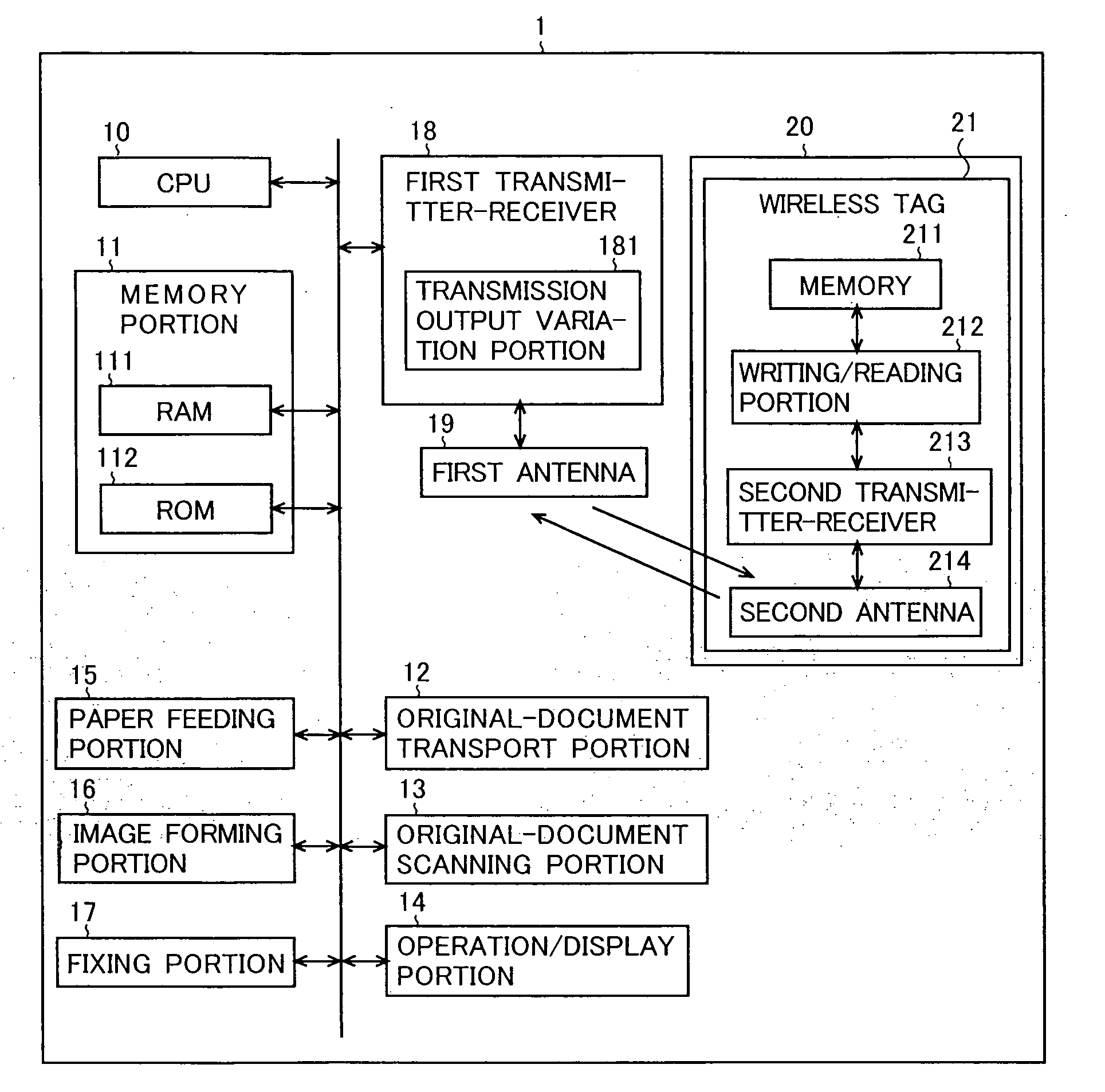
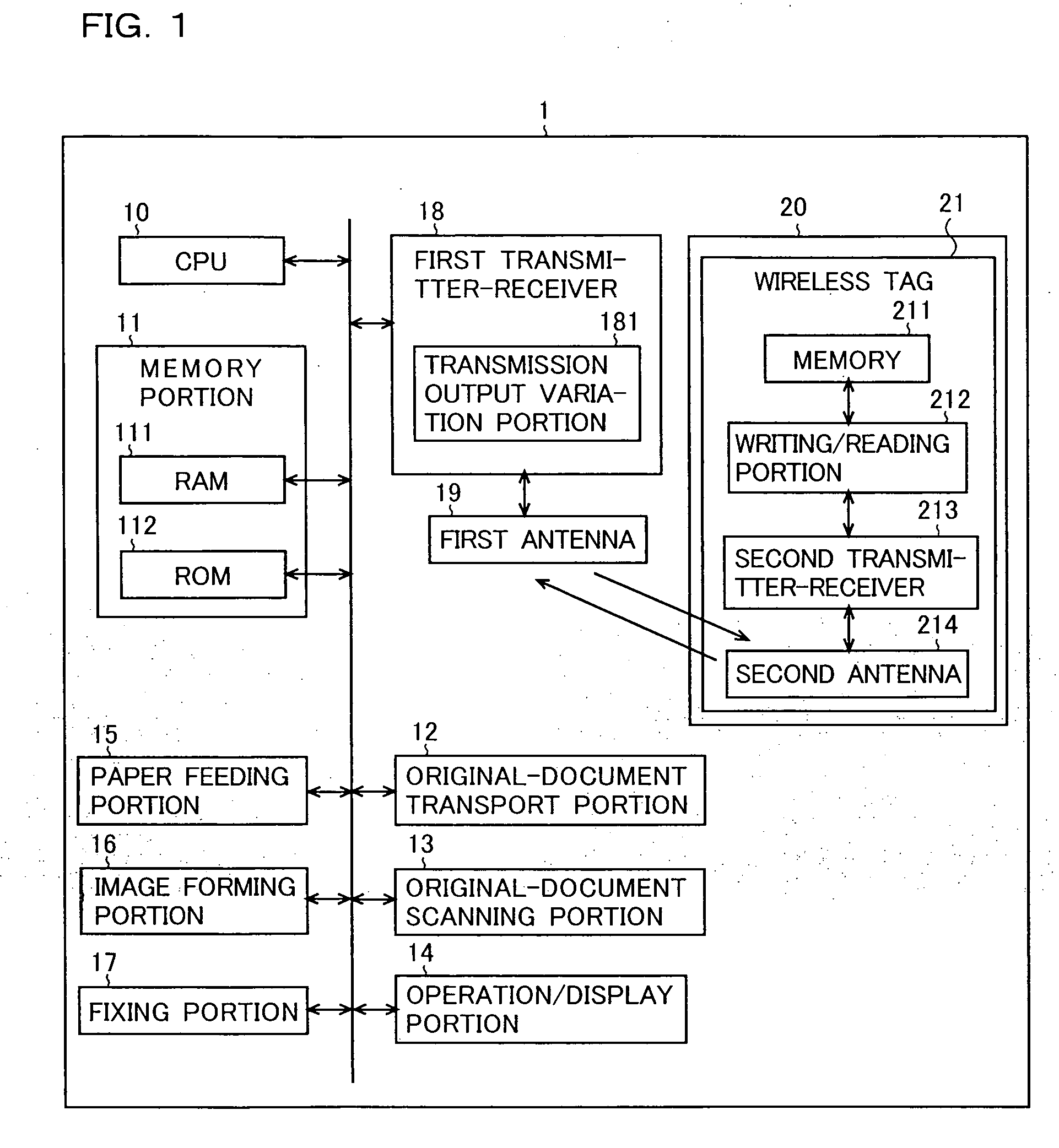
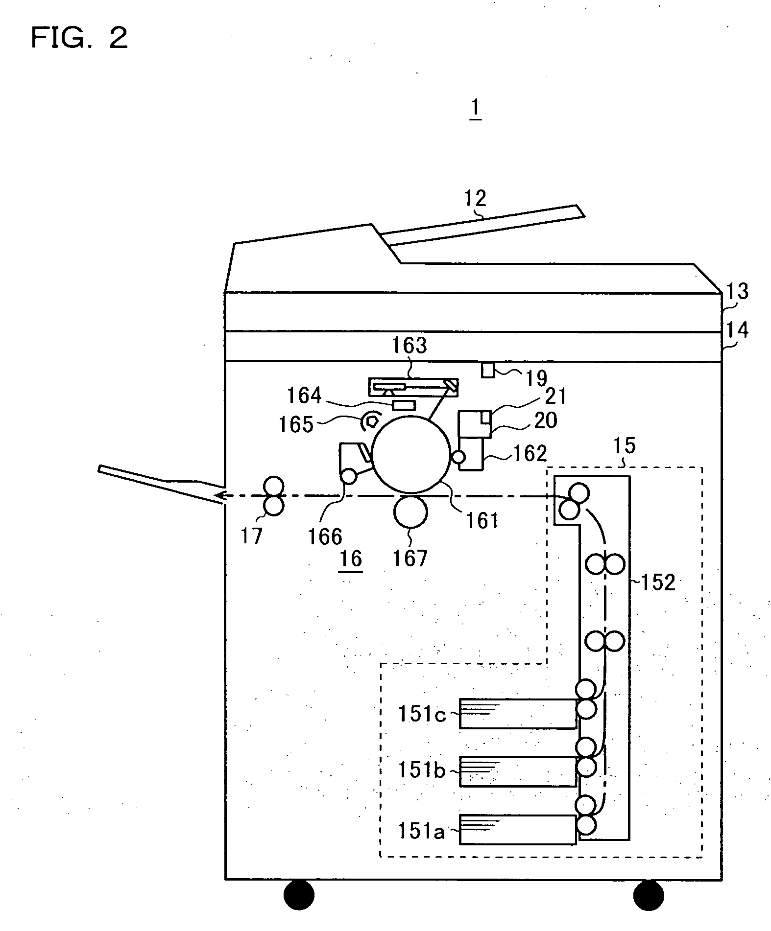
[0026] Hereinafter, an embodiment of the present invention will be described that deals with a case in which the present invention is applied to a copier. FIG. 1 is a block diagram showing the structure of a principal part of a copier according to the present invention and FIG. 2 is a vertical sectional view schematically showing the structure of a principal part of the copier according to the present invention. As shown in FIGS. 1 and 2, the copier 1 of this embodiment is provided with:

[0027] a central processing unit 10 (hereinafter referred to as CPU 10) for controlling the operation of the whole apparatus;

[0028] a memory portion 11 for storing a variety of control programs, data, and the like, and also for use as a work area;

[0029] a first transmitter-receiver 18 for performing RFID wireless communication with a wireless tag (described later);

[0030] a first antenna 19 that emits the transmission output of the first transmitter-receiver 18 into the air as electromagnetic wave...


PUM


Abstract

In a copier 1, when RFID wireless communication is performed between a first transmitter-receiver 18 and a wireless tag 21 fitted to a toner container 20, based on a table in which different transmission output values of the first transmitter-receiver 18 are written from the lower limit value to the upper limit value, wireless communication is first performed at the lower limit transmission output value, and if a CPU 10 finds that RFID wireless communication is not being performed properly, the first transmitter-receiver increases its transmission output stepwise according to the table until proper wireless communication is achieved.

Description

[0001] This application is based on Japanese Patent Application No. 2005-212905 filed on Jul. 22, 2005, the contents of which are hereby incorporated by reference. BACKGROUND OF THE INVENTION [0002] 1. Field of the Invention [0003] The present invention relates to reduction of leakage, out of an image forming apparatus, of electromagnetic wave noise that is emitted from RFID (radio-frequency identification) adopted in the image forming apparatus. [0004] 2. Description of Related Art [0005] Electromagnetic wave noise emitted from an electronic device adversely affects other electronic devices, and hence its emission is restricted with various standards (for example, those formulated by the Special International Committee on Radio Interference, with a French acronym “CISPR”). In image forming apparatuses, RFID compatible with such standards directed to electromagnetic wave noise is commonly adopted: typically, a reader / writer module (hereinafter referred to as R / W module) is fitted to...

Claims


Application Information

Patent Timeline
Patent Type & Authority Applications(United States)
IPC IPC(8): G06K15/22
CPCG03G2221/1823G03G21/1657G03G15/0863
Inventor KUSUMI, TADAHARU
Owner KYOCERA DOCUMENT SOLUTIONS INC
Why Eureka
Try Eureka