Sheet type common-mode choke row

A common mode choke and choke technology, applied in the field of chip common mode choke, can solve the problems of many electrode layers, low impedance peak frequency, etc., to simplify the process, high frequency range, reduce product cracking the effect of risk

Inactive Publication Date: 2012-07-11
SHENZHEN SUNLORD ELECTRONICS
View PDF5 Cites 3 Cited by
  • Summary
  • Abstract
  • Description
  • Claims
  • Application Information

AI Technical Summary

Problems solved by technology

[0006] It can be seen from Table 1 that to achieve a certain common-mode impedance for the common-mode choke row with the above structure, more electrode layers are required, and the impedance peak frequency is relatively low

Method used


Image

  • Sheet type common-mode choke row
  • Sheet type common-mode choke row
  • Sheet type common-mode choke row

Examples


Embodiment Construction

[0030] The present invention will be further described below with reference to the accompanying drawings and in combination with preferred embodiments.

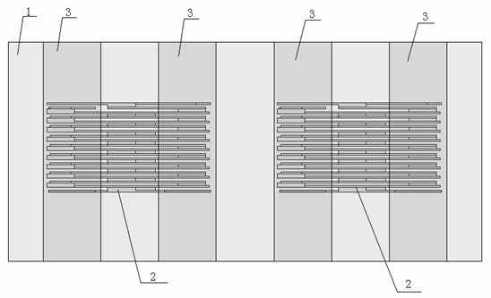
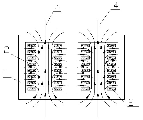
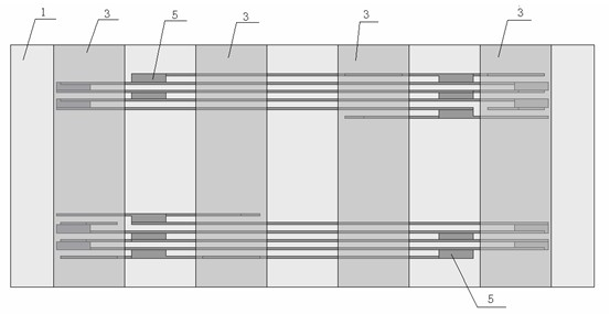
[0031] A chip common-mode choke row, comprising an upper substrate layer, a lower substrate layer, and at least two stacked common-mode chokes comprising coil layers with conductive coil patterns stacked between the upper substrate layer and the lower substrate layer The chokes are separated by the intermediate substrate layer between the upper and lower adjacent common mode chokes.

[0032] Such as Figure 3~7-5 As shown, the common mode choke row of this embodiment is in the form of a rectangular parallelepiped as a whole, including two chip common mode chokes, one of which (the upper coil) is located between the upper substrate layer 7 and the middle substrate layer 8, and the other The (lower coil) is located between the middle substrate layer and the lower substrate layer 9, and the common mode choke includes a multilay...


PUM


Abstract

The invention discloses a sheet type common-mode choke row, which comprises an upper substrate layer, a lower substrate layer and at least two stacked common-mode chokes, wherein the stacked common-mode chokes comprise coil layers provided with conductive coil patterns are and are stacked between the upper substrate layer and the lower substrate layer, and each two adjacent common-mode chokes are spaced by a middle substrate layer. Compared with the prior art, the arrangement of the two common-mode chokes are changed into vertical stacking, as shown as the picture 3, magnetic force lines of the coils of the two common-mode choke are identical in direction, and accordingly inductance of the single coil can be improved effectively. Meanwhile, when the stacking manner is compared with the horizontal arrangement, the coiled area of the coils is increased, the number of the coil layers for obtaining identical impedance is smaller, dispersion capacitance among layers is reduced, peak frequency can be increased by reducing the number of the coil layers, and the sheet type common-mode choke row can be applicable to the high-frequency range. Besides, occupation proportion of a non-overlapped area Z to the area of the coils is reduced, the area of an effective coupling area formed by the coils is increased, electromagnetic leakage is reduced, and difference-mode impedance of devices is lowered.

Description

technical field [0001] The invention relates to a chip common mode choke bank. Background technique [0002] Common mode chokes are commonly used devices for suppressing common mode noise in parallel lines. Combine two common mode chokes together to form a 2-in-1 common mode choke bank. figure 1 The structure shown is a two-in-one common mode choke row. This structure is to place two pairs of coils side by side in the horizontal plane, that is, to place two common mode chokes on the left and right sides of the product respectively to realize two common mode chokes. mode chokes form a common mode choke bank. However, if figure 2 As shown, in the above-mentioned chip common mode choke row, the two internal common mode chokes are horizontally arranged side by side, the magnetic field lines 4 interfere with each other, and the isolation between the two groups of coils is poor. At the same time, due to space constraints, the effective magnetic The pass area is limited, which...

Claims


Application Information

Patent Timeline
Patent Type & Authority Applications(China)
IPC IPC(8): H01F37/00H01F27/28H02J3/00
Inventor 漆珂石栋李森强庞新锋包承育伍隽郭海
Owner SHENZHEN SUNLORD ELECTRONICS
Why Eureka
Try Eureka