Inductive coupling plasma processor and plasma substrate processing method

An inductively coupled plasma technology, applied in the direction of plasma, circuit, discharge tube, etc., can solve problems such as temperature rise, uneven plasma density, energy loss, etc., to increase reliability and stability, and reduce RF Effect of electromagnetic leakage and reduction of electromagnetic interference

Active Publication Date: 2013-03-27
ADVANCED MICRO FAB EQUIP INC CHINA
View PDF8 Cites 4 Cited by
  • Summary
  • Abstract
  • Description
  • Claims
  • Application Information

AI Technical Summary

Problems solved by technology

[0004] However, the above-mentioned induced magnetic field generated by the first radio frequency source RF1 has the distribution of the magnetic force lines 410 as follows: figure 1 As shown by the dotted line in the middle, it can be seen that the uneven distribution of the magnetic force lines 410 above the substrate 30 will cause the plasma density corresponding to the center and edge positions of the substrate 30 to be uneven, thereby affecting the difference in radial direction on the substrate 30. Etch Uniformity of Position
[0005] In addition, because the induced magnetic field generated by the first radio frequency source RF1 is an open magnetic field, most of its energy is lost, and only a small part above the substrate 30 is used to generate the plasma, so the utilization efficiency of energy is low.
Moreover, most of the other unutilized magnetic field energy will produce interference, and these interferences have to be eliminated at a high cost; the unutilized magnetic field energy will also induce heat, which will increase the temperature of the entire plasma generator. High, reducing the service life of the device and the stability of the etching operation

Method used


Image

  • Inductive coupling plasma processor and plasma substrate processing method
  • Inductive coupling plasma processor and plasma substrate processing method
  • Inductive coupling plasma processor and plasma substrate processing method

Examples


Embodiment 1

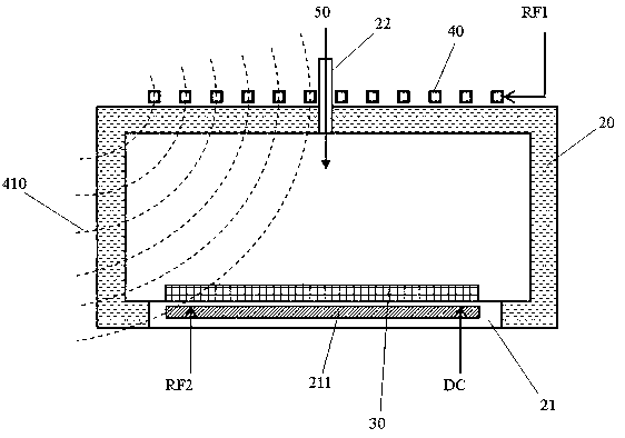
[0065] Cooperate see figure 2 , image 3 , Figure 4 As shown, the inductively coupled plasma processing device (ICP) in the present invention includes a vacuum reaction chamber 20 into which a reaction gas 50 is introduced. The top of the reaction chamber 20 is provided with an induction coil 40, which is connected with the first radio frequency source RF1 to generate an induction magnetic field, and induces a radio frequency electric field in the axial direction of the coil, thereby generating the said coil in the reaction chamber 20. Plasma of reactive gas 50 . The bottom of the reaction chamber 20 is provided with an electrostatic chuck 21 (ESC) and a base for fixing the substrate 30 .

[0066] As an improvement to the inductively coupled plasma processing device (ICP), the present invention also includes a magnetic field line adjustment component 10, which is made of a magnetically permeable material whose magnetic permeability is 10 times or more than that of air; du...

Embodiment 2

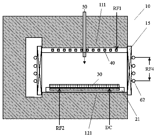
[0074] Cooperate see Figure 5 , 6 , 9, the overall structure of the inductively coupled plasma processing device (ICP) described in this example is similar to that in Example 1, including transformer-type, quasi-closed or barrel-type magnetic lines of force arranged around the reaction chamber 20 The adjustment part 10 is made of low reluctance magnetic materials such as ferrite; the induction coil 40 arranged on the outside of the top of the reaction chamber 20 is connected to most of the magnetic field lines of the induced magnetic field generated after the first radio frequency source RF1 flows through The magnetic flux adjusting component 10 and the structure of the magnetic flux adjusting component 10 determine the distribution of the magnetic flux inside and outside the reaction chamber 20 . Preferably, the magnetic field lines above the substrate 30 in the reaction chamber 20 are uniformly and linearly distributed to improve the uniformity of the plasma distribution o...

Embodiment 3

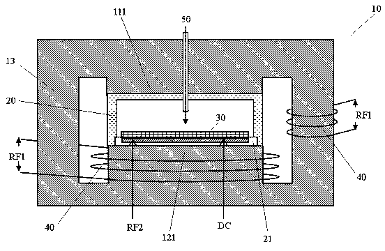
[0079] Cooperate to participate Figure 7 , 8 , 10, the overall structure of the inductively coupled plasma processing device (ICP) described in this example is similar to that in Embodiments 1 and 2, including transformer-type, quasi-closed-type or barrel-type surrounding the reaction chamber 20 The magnetic field line adjustment part 10, which is made of low reluctance magnetic material such as ferrite; the induction coil 40 arranged outside the top of the reaction chamber 20, most of the magnetic field lines of the induced magnetic field generated after connecting the first radio frequency source RF1 The magnetic force lines flow through the adjustment component 10 , and the distribution of the magnetic force lines inside and outside the reaction chamber 20 is determined by the structure of the magnetic force line adjustment component 10 . Preferably, the magnetic field lines above the substrate 30 in the reaction chamber 20 are uniformly and linearly distributed to improv...


PUM


Abstract

The invention relates to an inductive coupling plasma processor and a plasma substrate processing method. A magnetic line adjusting component made of magnetic materials is disposed to form a close-preparing low magnetic resistance passage as the passage for circulating of a magnetic line loop outside a reaction cavity. The low magnetic resistance passage standardizes most magnetic line paths in an induced magnetic field to collect originally divergent magnetic energy, so that magnetic field intensity of the reaction cavity can be doubled. Or, plasma for processing can be generated at the same magnetic field intensity utilizing less energy, so that energy utilization efficiency is improved. In addition, RF (radio frequency) electromagnetic leakage is reduced evidently, electromagnetic interference to environments is reduced, heat generation of equipment is reduced, and system reliability and stability is increased. The magnetic line adjusting component is provided two protrusions extending oppositely and corresponding to two magnetic poles, and accordingly magnetic lines between the two magnetic poles are distributed uniformly and linearly, and uniformity of plasma distribution on the surface of a substrate is improved.

Description

technical field [0001] The invention relates to an inductively coupled plasma processing device and a substrate processing method thereof, in particular to an inductively coupled plasma processing device and a substrate processing method that can standardize the path of magnetic force lines to collect divergent energy. Background technique [0002] Currently, in the manufacturing process of semiconductor devices, an inductively coupled plasma processing device (ICP) is usually used to generate the plasma of the reactive gas 50 to perform processing such as etching on the substrate 30 . [0003] Such as figure 1 As shown in , the conventional inductively coupled plasma generator (ICP) usually introduces the reaction gas 50 into the vacuum reaction chamber 20 . An induction coil 40 is provided on the top (or bottom or side wall) of the reaction chamber 20, and the first radio frequency source RF1 is applied, and the resulting induced magnetic field will induce a radio frequen...

Claims


Application Information

Patent Timeline
Patent Type & Authority Applications(China)
IPC IPC(8): H05H1/46
CPCH01J37/3266H01J37/32669H01J37/321
Inventor 刘忠笃
Owner ADVANCED MICRO FAB EQUIP INC CHINA
Why Eureka
Try Eureka