Magnetic head, fabrication process of magnetic head, and magnetic disk storage apparatus mounting magnetic head

a technology of magnetic storage and fabrication process, which is applied in the direction of magnetic recording, magnetic recording head, instruments, etc., can solve the problems of noise source, noise source, noise source, etc., and achieve the effect of high output, low noise, and high recording density of magnetic storag

Inactive Publication Date: 2007-02-08
HITACHI GLOBAL STORAGE TECH NETHERLANDS BV
View PDF11 Cites 8 Cited by
  • Summary
  • Abstract
  • Description
  • Claims
  • Application Information

AI Technical Summary

Benefits of technology

[0021] In the case of conventional magnetic heads, these two problems lower the manufacturing yield of the read sensor. A feature of the present invention is to solve these problems.
[0025] According to the present invention, the structure that prevents the side wall of the magnetoresistance layer from exposing to avoid any leakage of the sense current may be built by the lift-off process using CMP and a step formed at the point where the refill film along the sensor height direction comes in contact with the magnetoresistance layer may be reduced, achieving the magnetic head of high output but low noise. Moreover, mounting the magnetic head of the present invention achieves a high-recording density of magnetic storage. Furthermore, the manufacturing yield of the magnetic head may be improved.

Problems solved by technology

If the read sensor is fabricated into such a shape, two problems described below may arise.
One is the degradation of output due to leakage of the sense current.
The other problem is that a magnetic domain of the upper shield layer 2 is easily formed in the vicinity of magnetoresistance layer 3 due to a step occurring in the upper shield layer 2.
This magnetic domain of the upper shield layer 2 possibly causes a noise source.
Accordingly, this step causes the magnetic domain to be formed in the upper shield layer 2, possibly causing a noise source.

Method used


Image

  • Magnetic head, fabrication process of magnetic head, and magnetic disk storage apparatus mounting magnetic head
  • Magnetic head, fabrication process of magnetic head, and magnetic disk storage apparatus mounting magnetic head
  • Magnetic head, fabrication process of magnetic head, and magnetic disk storage apparatus mounting magnetic head

Examples


Embodiment Construction

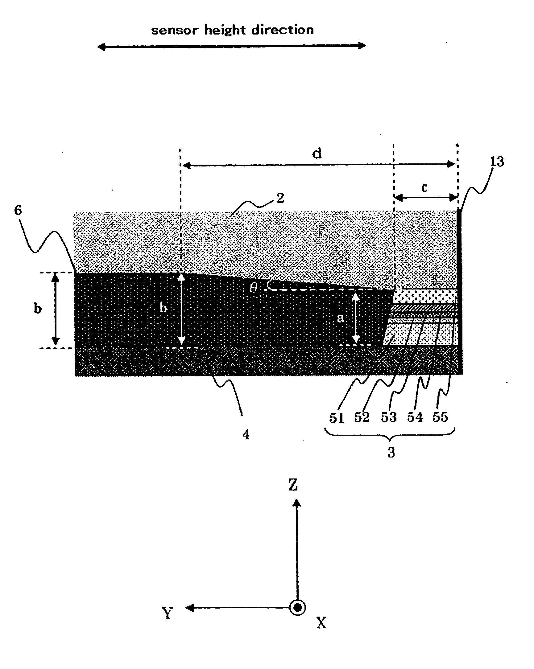
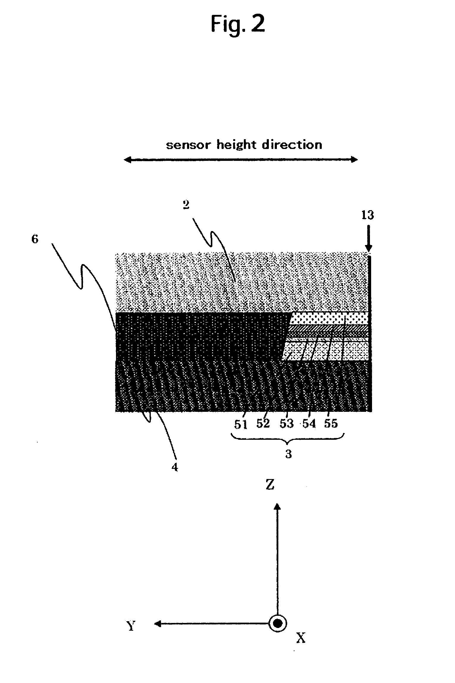
[0047]FIG. 9 shows an example of a cross sectional structure along the sensor height direction of the magnetic head of the present invention. The magnetic head of the present invention basically meets three structural requirements described below.

[0048] (1) The refill film along the sensor height direction 6 is in contact with the ends of all the layers closer to the lower shield layer 4 than to the intermediate layer 53 of the magnetoresistance layer 3.

[0049] (2) The distance from the upper surface of the refill film along the sensor height direction 6 to the upper surface of the lower shield layer 4 (in other words, the length of a perpendicular drawn from the upper surface of the refill film along the sensor height direction 6 to the upper surface of the lower shield layer 4) is shortest at the point where the refill film along the sensor height direction 6 comes in contact with the magnetoresistance layer 3 (in other words, at the closest position to the upper shield layer 2 a...


PUM

PropertyMeasurementUnit
angleaaaaaaaaaa
distanceaaaaaaaaaa
lengthaaaaaaaaaa

Abstract

This invention provides a high-output magnetic head with a high yield, which is capable of minimizing sense current leak or noise caused by a shift of the magnetic wall of an upper shield layer. In one embodiment, the magnetic head is fabricated so that the height of the upper surface of the refill film along the sensor height direction is the same as that of the magnetoresistance layer in a portion where the refill film along the sensor height direction comes in contact with the magnetoresistance layer and the distance from the upper surface of the refill film along the sensor height direction to the upper surface of the lower shield layer gradually increases in a region from the portion where the refill film along the sensor height direction comes in contact with the magnetoresistance layer to a point at a certain distance away from the portion.

Description

CROSS-REFERENCES TO RELATED APPLICATIONS [0001] This application claims priority from Japanese Patent Application No. JP2005-228055, filed Aug. 5, 2005, the entire disclosure of which is incorporated herein by reference. BACKGROUND OF THE INVENTION [0002] The present invention relates to a magnetic head that reads magnetically recorded data, the process of fabricating the magnetic head, and magnetic disc storage apparatus mounting the magnetic head and in particular to a magnetic head having a high S / N ratio and a high yield and a magnetic disc storage apparatus mounting the magnetic head. [0003] A magneto-resistive sensor using a magnetoresistance effect, which causes electrical resistance to vary with a change in an external magnetic field, is known to be an excellent magnetic field sensor and therefore, it has been put into practical use as a read sensor for detecting a signal magnetic field from a magnetic recording medium storage in the magnetic head, an important part of the m...

Claims


Application Information

Patent Timeline
Patent Type & Authority Applications(United States)
IPC IPC(8): G11B5/33
CPCG11B5/3163G11B5/398G11B5/3912G11B5/3909G11B2005/3996
Inventor SHINTANI, TAKUWATANABE, KATSUROYOSHIDA, NOBUOTAKEI, HISAKO
Owner HITACHI GLOBAL STORAGE TECH NETHERLANDS BV
Why Eureka
Try Eureka