Passive fan assembly

a passive fan and fan body technology, applied in the direction of machines/engines, stators, liquid fuel engines, etc., to achieve the effect of effectively using airflow and promoting heat dissipation efficiency

Inactive Publication Date: 2007-02-08
DELTA ELECTRONICS INC
View PDF14 Cites 22 Cited by
  • Summary
  • Abstract
  • Description
  • Claims
  • Application Information

AI Technical Summary

Benefits of technology

[0011] The passive fan assembly of the invention is capable of effectively using the airflow and promoting the heat-dissipating efficiency.

Problems solved by technology

More motors used in the electronic system indicate more power has to be provided and consumed, which does not conform to the trend of saving power.

Method used


Image

  • Passive fan assembly
  • Passive fan assembly
  • Passive fan assembly

Examples


Embodiment Construction

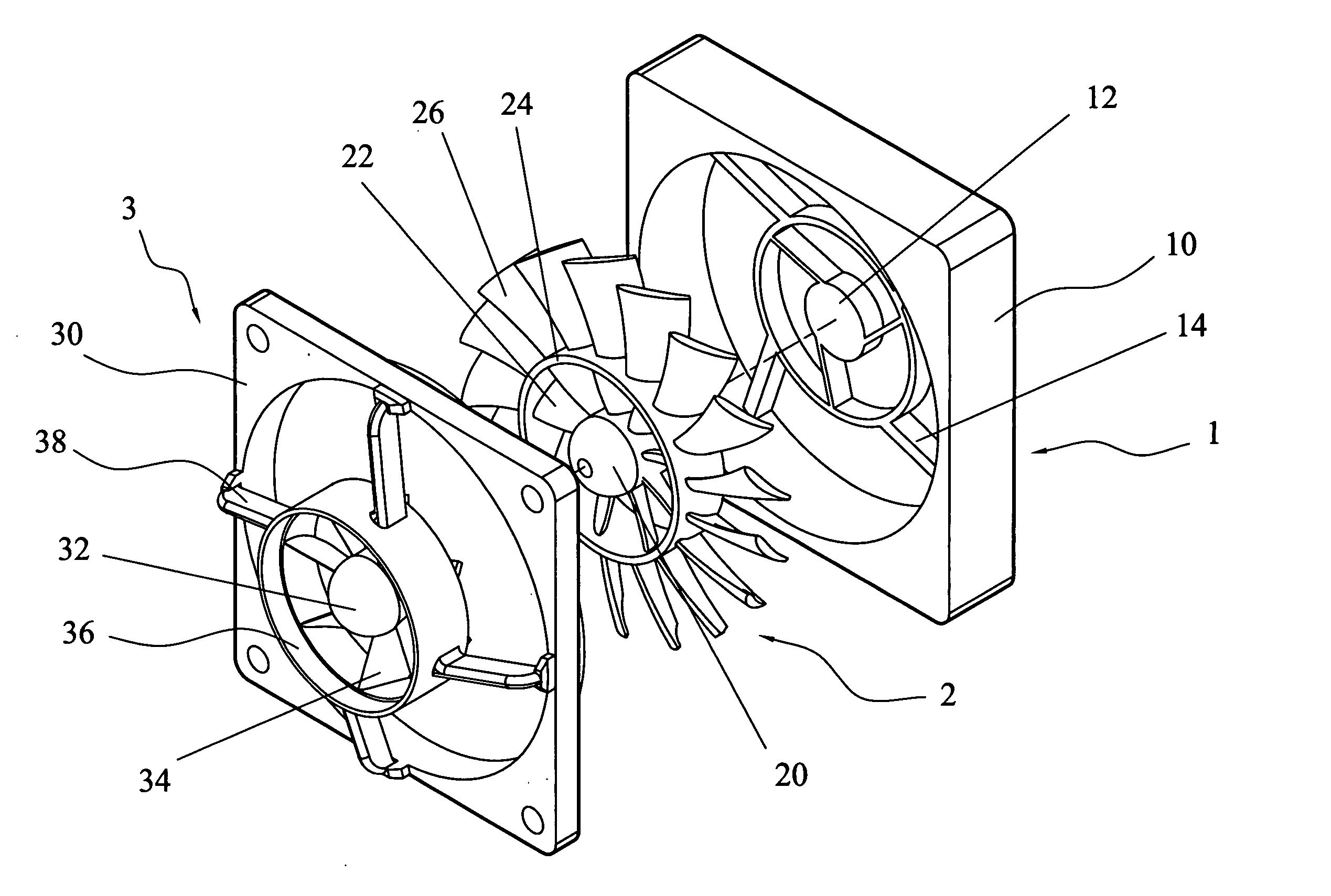
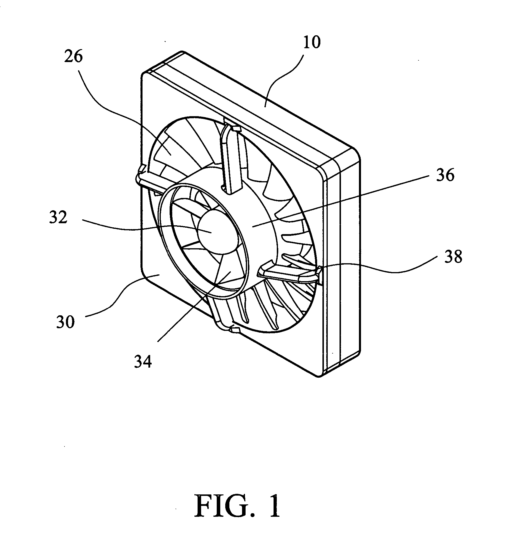
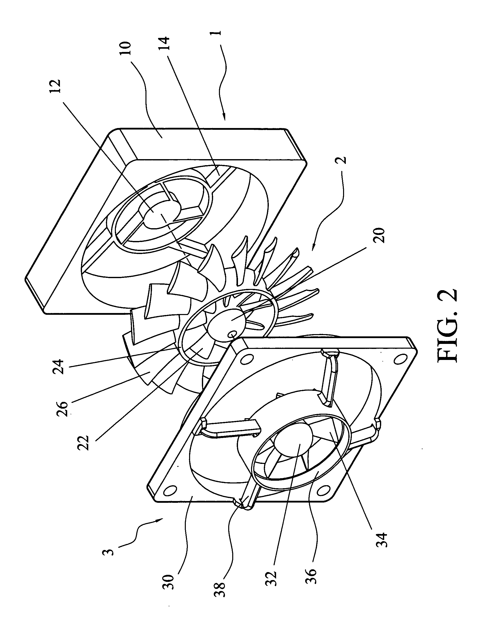
[0019] Referring to FIGS. 1, 2 and 4, a passive fan assembly in accordance with an embodiment of the invention includes a base 1, an impeller 2 mounted on the base 1, and a cover 3 disposed in front of the impeller 2 and connected to the base 1.

[0020] The impeller 2 includes a hub 20, a plurality of runner blades 22 encircling the hub 20, a partition 24 connected to ends of the runner blades 22, a plurality of active blades 26 encircling the partition 24, and a rotary shaft 28 axially extending from the hub 20.

[0021] The base 1 includes a frame 10, a bearing seat 12, a plurality of ribs 14 connecting the frame 10 and the bearing seat 12, and at least one bearing 16 disposed in the bearing seat 12 for holding the rotary shaft 28 of the impeller 2. The bearing 16 may be a bushing bearing, a ball bearing, a magnetic bearing or any other bearing in which the rotary shaft 28 can be stably rotated. Furthermore, a plurality of airflow-guiding blades can be substituted for the ribs 14 in ...


PUM


Abstract

A passive fan assembly includes an impeller and a plurality of guide blades disposed in front of the impeller. The impeller includes a plurality of blades extending at about 90 degrees relative to the guide blades. Thus, when airflow enters the passive fan assembly, the guide blades guide the airflow to effectively impact on blades of the impeller.

Description

BACKGROUND [0001] The invention relates to a passive fan assembly, and in particular, to a passive fan assembly provided with guide blades for increasing the kinetic energy received by the impeller of the assembly in operation and promoting the efficiency of energy transfer. [0002] Generally, a fan is used together with a motor. The motor rotates the fan to dissipate heat. [0003] A conventional fan presents the following drawbacks. A fan and a motor are generally used together, thus, a consumer must pay for the motor and the fan. The motor, coupled to a fan, occupies additional space even if the size of the motor is minimized. Moreover, if the components to be cooled are disposed in different locations in an electronic system, more than one fan and motor are required. More motors used in the electronic system indicate more power has to be provided and consumed, which does not conform to the trend of saving power. [0004] Thus, a passive fan assembly capable of providing an improved h...

Claims


Application Information

Patent Timeline
Patent Type & Authority Applications(United States)
IPC IPC(8): F01D9/00
CPCF04D29/542F04D25/08F04D29/544
Inventor HSU, CHIA-MINGCHANG, SHUN-CHENHUANG, WEN-SHI
Owner DELTA ELECTRONICS INC
Why Eureka
Try Eureka