Thermal catalytic ignition system for airborne applications

a catalytic ignition and airborne technology, applied in the direction of electric fuzes, lighting and heating apparatus, separation processes, etc., can solve the problems of toxic and a suspected carcinogen, low density of fuel and air storage, and the tendency of jet fuel and air systems to impose a greater weight penalty on airborne systems, etc., to promote the reaction

Inactive Publication Date: 2007-02-08
HONEYWELL INT INC
View PDF6 Cites 16 Cited by
  • Summary
  • Abstract
  • Description
  • Claims
  • Application Information

AI Technical Summary

Benefits of technology

[0015] In another aspect of the invention, an ignition apparatus is provided for promoting the reaction of a monopropellant that is passed over a catalyst bed having a first portion and a second portion. The ignition apparatus comprises a resistive heating element with a resistance, the resistive heating element being associated with the first portion of the catalyst bed; and a capacitor having sufficient capacity to hold a charge, the capacitor arranged to discharge the charge across the resistive heating element, with the resistance and the charge chosen to maintain the resistive heating element at a selected temperature for a selected duration of time. This apparatus causes the monopropellant to react when passed over the first portion of the catalyst bedfor the selected duration of time.
[0016] In still another aspect of the invention, a thermal ignition system is provided for igniting a monopropellant to produce a hot gas. The system comprises a reactor with a catalyst bed, where the catalyst bed has a first portion and a second portion and the monopropellant is directed across the first portion and the second portion; a resistive heating element associated with the first portion; and a power source providing current to the resistive heating element. This arrangement allows the temperature of the first region to be elevated and the reaction of the monopropellant to occur over the first portion before the reaction of the monopropellant over the second portion.

Problems solved by technology

It is also toxic and a suspected carcinogen.
However, because the density of the fuel and air storage is relatively low, such jet fuel and air systems require a greater volume to meet a given duty cycle than hydrazine-based systems.
Jet fuel and air systems also tend to impose a greater weight penalty for airborne systems due to the added weight of the air storage vessels.
However, current catalyst formulations do not perform well at temperatures as low as about −54° C. and are unable to achieve reaction of the fuel without auxiliary heating of the catalytic bed.
This auxiliary heating requires additional energy over hydrazine-based systems, which in turn complicates ignition system design.
However, a capacitive discharge system of this kind is not used to heat a catalytic bed but is used to vaporize a fuel source, and thus would not be useful in igniting a monopropellant.
In order to operate a catalytic ignition EPU system in environments having temperatures of 80° C. or below, it is necessary to use a highly reactive catalyst containing noble metals such as platinum or iridium, which are expensive.
Alternatively, a less reactive catalyst may be used, but this requires a highly reactive fuel such as hydrazine for the desired reaction; hydrazine is both highly reactive and toxic.

Method used


Image

  • Thermal catalytic ignition system for airborne applications
  • Thermal catalytic ignition system for airborne applications
  • Thermal catalytic ignition system for airborne applications

Examples


Embodiment Construction

[0021] The following detailed description is of the best currently contemplated modes of carrying out the invention. The description is not to be taken in a limiting sense, but is made merely for the purpose of illustrating the general principles of the invention, since the scope of the invention is best defined by the appended claims.

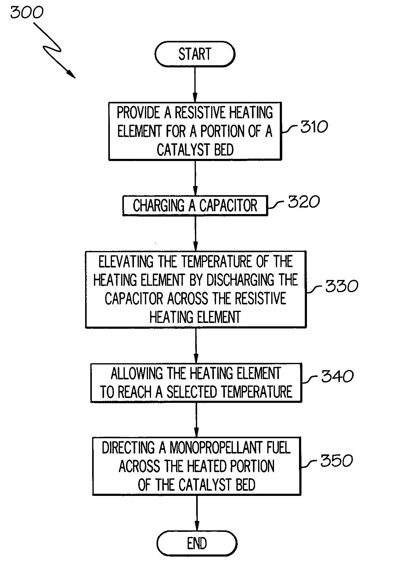
[0022] The invention may find application in the area of airborne emergency power systems, where the system may be powered by a monopropellant fuel that may be reacted by catalytic action in a catalytic reactor. The invention may be used when a loss of power may necessitate the rapid initiation of an EPU in airborne applications where weight and operation under low temperature conditions are a consideration. The invention may find additional application as orbital alignment thrusters for use in satellites or spacecraft.

[0023] The environment in which such systems must operate has a temperature as low as about −54° C., but the reaction of such monopro...


PUM

PropertyMeasurementUnit
temperatureaaaaaaaaaa

Abstract

A power source is provided for a resistive heating element that heats a catalyst bed of a reactor that receives a monopropellant fuel and reacts the fuel in the presence of the catalyst bed to provide hot gas driving a turbine. The power source is a capacitor that discharges its charge across the resistive heating element so that its temperature is elevated to a point where the reaction of the monopropellant fuel occurs. The power source may be used in airborne applications, such as emergency power systems for aircraft, where it is desirable to minimize the weight of the unit and to allow the unit to use safer monopropellant fuels.

Description

BACKGROUND OF THE INVENTION [0001] The present invention relates generally to the area of airborne power systems, and more particularly to an apparatus and method for the rapid reaction of monopropellant fuels in the presence of a catalyst bed to provide a hot gas for driving a turbine. [0002] Modern day aircraft are generally provided with Emergency Power Unit (EPU) systems designed to provide power to other aircraft systems in the event of an engine failure. Such systems must be capable of ignition at temperatures as low as about −54° C. because of the environmental conditions within which the aircraft must operate. Although many different propellants have been considered for use in EPU systems, only two are currently being used, namely, either H-70 monopropellant or a bipropellant consisting of jet fuel and air. Although the term “ignition” may be commonly used to describe a reaction of either propellant, the term “ignition” in its strictest sense may be used to describe the init...

Claims


Application Information

Patent Timeline
Patent Type & Authority Applications(United States)
IPC IPC(8): B01D50/00
CPCF02K9/50F05D2220/50F02K9/95B64D41/00
Inventor KAISER, MARKJOHNSON, RUSSKOERNER, MIKE S.
Owner HONEYWELL INT INC
Why Eureka
Try Eureka