Eureka AIR delivers breakthrough ideas for toughest innovation challenges, trusted by R&D personnel around the world.

Apparatus, system and methods for deadfront visible loadbreak

a technology of visible loadbreak and apparatus, applied in the field of separate loadbreak connector systems, can solve problems such as complicated us

Inactive Publication Date: 2007-02-08
EATON INTELLIGENT POWER LTD
View PDF6 Cites 53 Cited by
  • Summary
  • Abstract
  • Description
  • Claims
  • Application Information

AI Technical Summary

Benefits of technology

[0009] According to another embodiment, a method of visibly breaking an electrical connection to a deadfront electrical apparatus is provided. The method comprises providing first and second electrical connectors, one of the connectors being fixed to the apparatus and the other of the connectors movable thereto, and one of the connectors including an arc follower and the other of the connectors including an arc interrupter. The method also includes joining the first and second electrical connectors under energized circuit conditions to complete the electrical connection to the apparatus, separating the first and second electrical connectors to disconnect the electrical connection to the apparatus, and limiting the separation of the first and second electrical connectors so that the arc follower remains within the arc interrupter and arc energy substantially remains in an interior of the connectors.
[0010] According to another embodiment, a method of visibly breaking an electrical connection to a deadfront electrical apparatus is provided. The method comprises providing first and second electrical connector assemblies, at least one of the connectors having first and second contact elements connected to a bus, thereby providing a series connection between the first and second contact elements. The method also includes joining the first and second electrical connectors under energized circuit conditions to complete the electrical connection to the apparatus, and simultaneously breaking electrical arcing at the first and second contact element.

Problems solved by technology

While such connector systems for deadfront apparatus can be effective to provide the visible break, they can be complicated to use, and generally require that the cables be de-energized prior to operation of the connectors.

Method used


Image

  • Apparatus, system and methods for deadfront visible loadbreak
  • Apparatus, system and methods for deadfront visible loadbreak
  • Apparatus, system and methods for deadfront visible loadbreak

Examples


Embodiment Construction

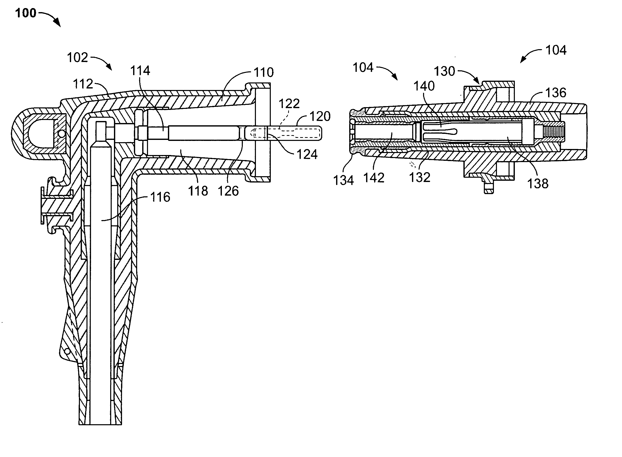
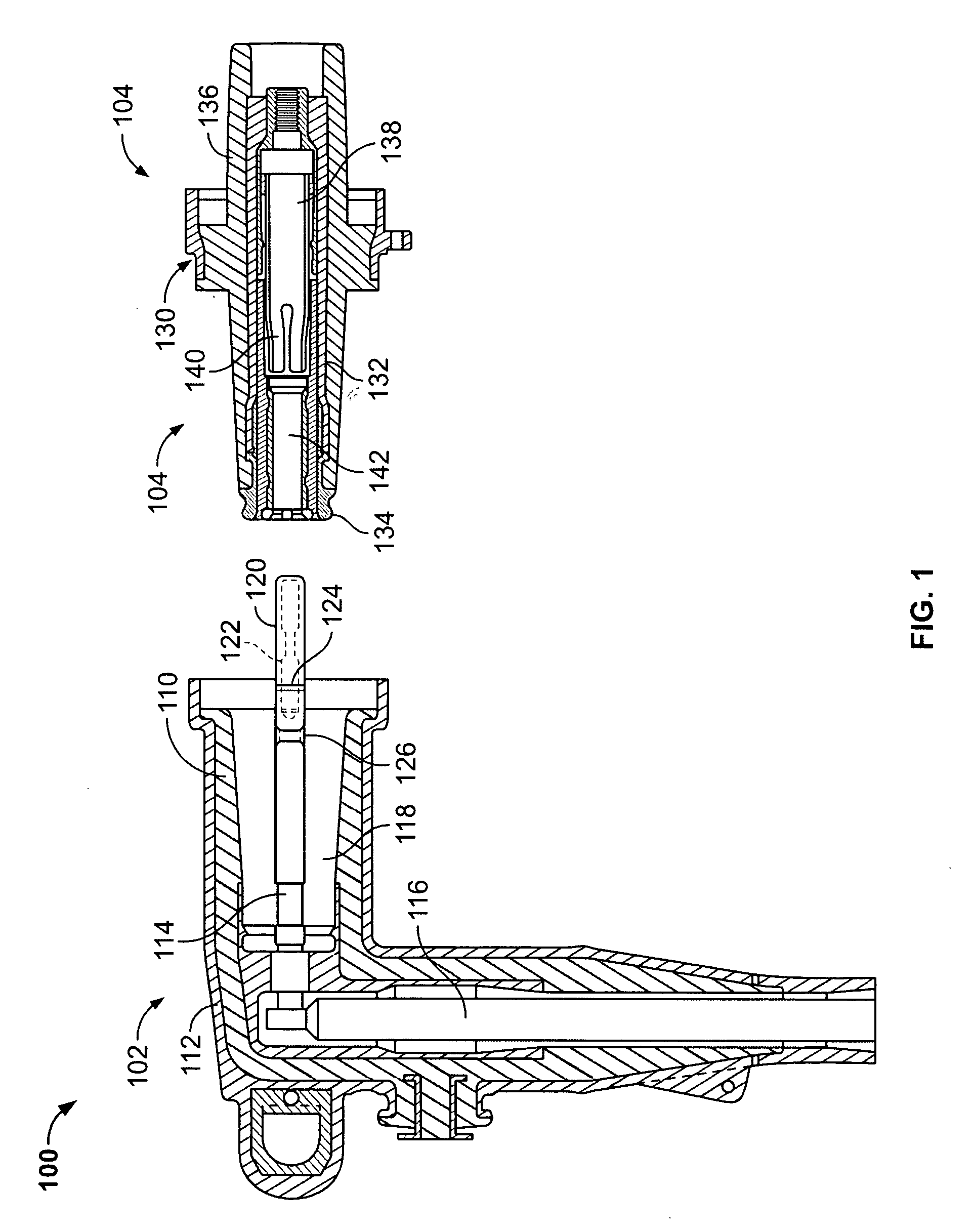
[0020]FIG. 1 is a longitudinal cross-sectional view of a separable loadbreak connector system 100, the type of which may be employed in an assembly according to the present invention.

[0021] As shown in FIG. 1, the system 100 includes a female connector 102 and a male connector 104 for making or breaking an energized connection in a power distribution network. The male connector 104 may be, for example, a bushing insert or connector connected to a deadfront electrical apparatus such as a capacitor, a transformer, switchgear or other electrical apparatus for connection to the power distribution network, and the female connector 102, may be, for example, an elbow connector, electrically connected to a power distribution network via a cable (not shown). The female and male connectors 102, 104 respectively engage and disengage one another to achieve electrical connection or disconnection to and from the power distribution network.

[0022] While the female connector 102 is illustrated as ...


PUM


Abstract

A loadbreak connector system and methods for visible break include first and second mating connector assemblies configured to make or break an electrical connection under energized circuit conditions, the first and second mating connectors selectively postionable relative to one another. One of the first and second mating connectors includes an arc follower, and the other of the first and second mating connectors includes an arc interrupter. The arc interrupter is configured to receive the arc follower, and the first and second meting connectors are positionable in an disconnected position wherein the arc follower remains engaged to and is located within the arc interrupter. Arc energy is distributed among multiple locations to reduce arc intensity.

Description

BACKGROUND OF THE INVENTION [0001] The invention relates generally to separable loadbreak connector systems for electric power systems, and more particularly to insulated loadbreak connector systems to interface deadfront electrical apparatus and power distribution cables. [0002] Electrical power is typically transmitted from substations through cables which interconnect other cables and electrical apparatus in a power distribution network. The cables are typically terminated on bushings that may pass through walls of metal encased equipment such as capacitors, transformers or switchgear. [0003] Because of increased safety, increased reliability and increased operability of the deadfront system, deadfront electrical apparatus is increasingly being used in lieu of livefront apparatus Using a deadfront system, because there is no exposed voltage, safety is increased for both the operator and the public, and the ability to operate the apparatus easily and efficiently either with ground...

Claims


Application Information

Patent Timeline
Patent Type & Authority Applications(United States)
IPC IPC(8): H01R13/53
CPCH01H9/085H01H31/24H01R13/111H01R2101/00H01R13/637H01R13/641H01R13/53
Inventor HUGHES, DAVID CHARLESSTEINBRECHER, BRIAN TODD
Owner EATON INTELLIGENT POWER LTD
Why Eureka
Eureka Blog
Learn More