Refrigerator and control method thereof

a technology of refrigerator and control method, which is applied in the field of refrigerators, can solve the problems of shortage of total amount of circulating refrigerant, and lowering the cooling efficiency, and achieve the effect of improving the cooling efficiency

Inactive Publication Date: 2007-02-15
SAMSUNG ELECTRONICS CO LTD
View PDF6 Cites 35 Cited by
  • Summary
  • Abstract
  • Description
  • Claims
  • Application Information

AI Technical Summary

Benefits of technology

[0015] Accordingly, it is an aspect of the present invention to provide a refrigerator which independently cools three or more storage compartments and improves cooling efficiency, and a control method thereof.

Problems solved by technology

However, because the plurality of evaporators are connected with each other in parallel in the cooling loop of the conventional refrigerator, when the refrigerant from the compressor is simultaneously supplied to the plurality of evaporators, the evaporator with small internal resistance receives more refrigerant than that with relatively high internal resistance, thereby lowering the cooling efficiency.
In the cooling loop of the conventional refrigerator, if the refrigerant supplied from the compressor by the valve is supplied to some of the plurality of the evaporators, some already distributed refrigerant may be stuck in the evaporator which does not receive refrigerant from the compressor, thereby causing a shortage in the total amount of the circulating refrigerant and lowering of the cooling efficiency.
However, if the valve mounted in the refrigerant pipe is open in the refrigerator having the plurality of evaporators, the refrigerant is continuously introduced to the plurality of evaporators while defrosting the refrigerator, thereby taking a relatively long time to remove the frost, and lowering the cooling efficiency as the heat generated while defrosting the refrigerator is transferred to the storage compartments and the refrigerant.

Method used


Image

  • Refrigerator and control method thereof
  • Refrigerator and control method thereof
  • Refrigerator and control method thereof

Examples


Embodiment Construction

[0038] Reference will now be made in detail to the present preferred embodiment of the present invention, an example of which is illustrated in the accompanying drawings, wherein like reference numerals refer to like elements throughout.

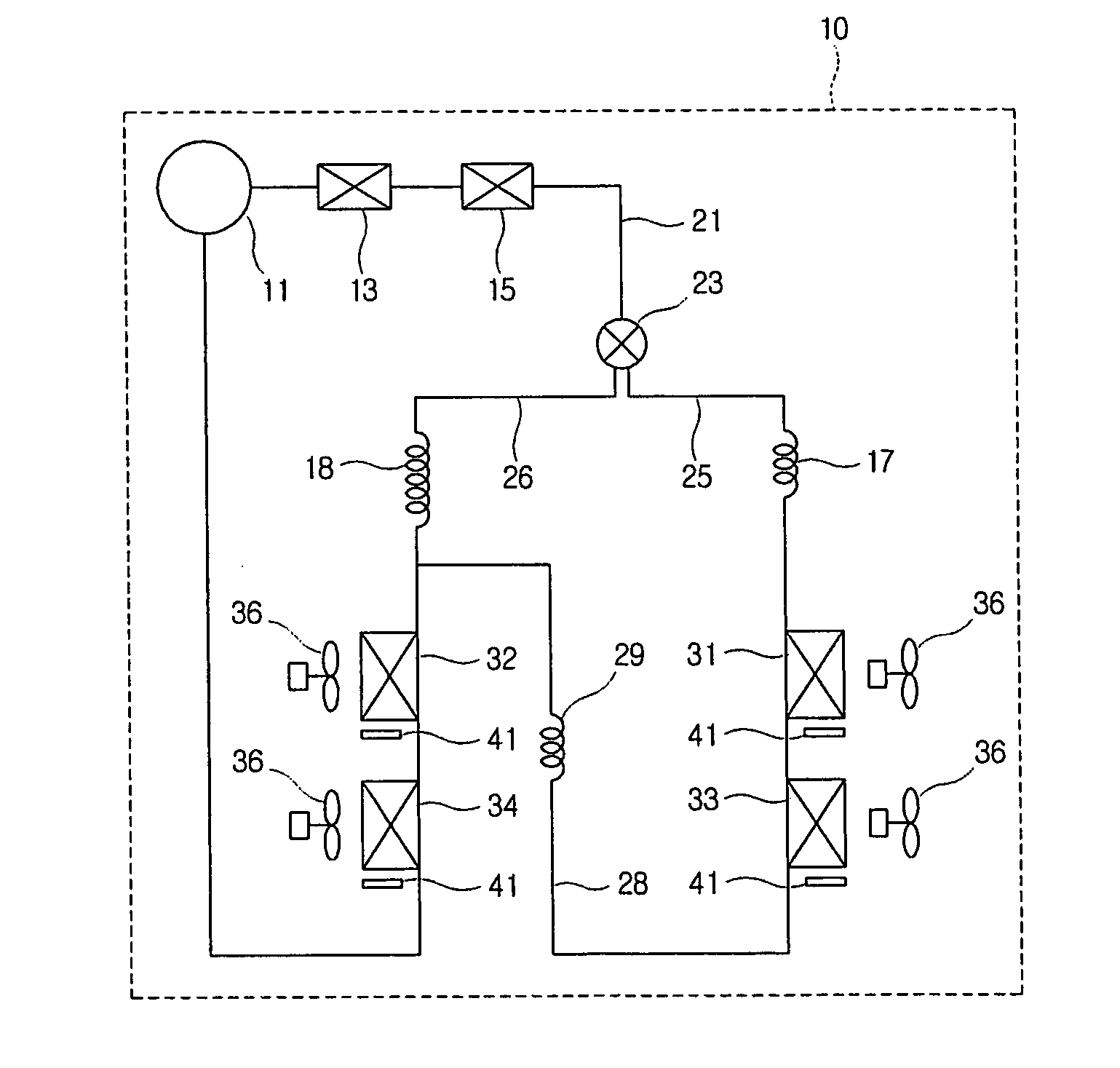
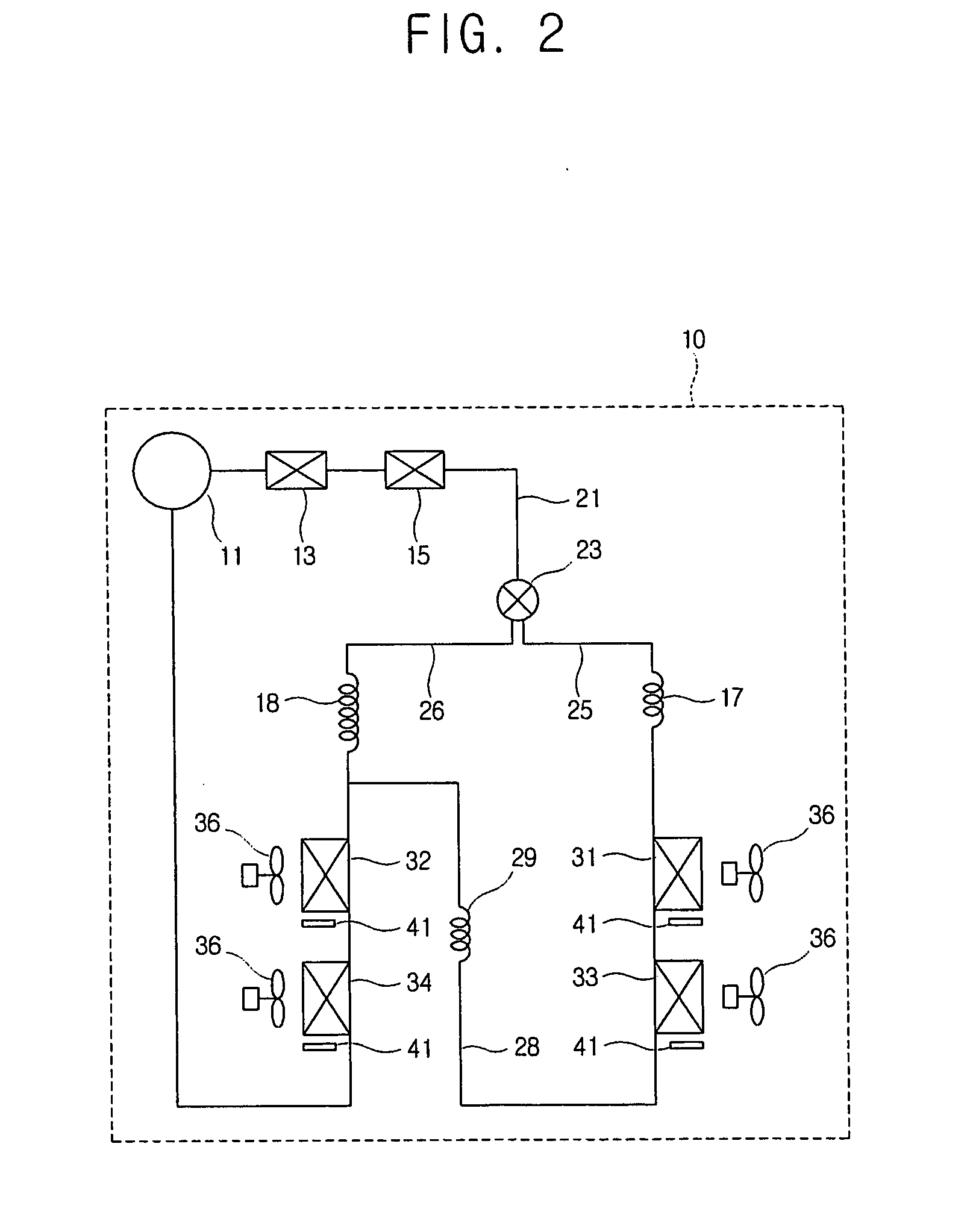
[0039] A refrigerator according to the embodiment of the present invention comprises a main body (not shown) which is formed with three or more storage compartments (not shown); and a plurality of doors (not shown) which open and close the respective storage compartments. As shown in FIG. 2, a cooling unit 10 comprises a plurality of evaporators 31, 32, 33 and 34 respectively corresponding to the respective storage compartments.

[0040] As an example, the present invention includes four storage compartments to respectively correspond to the four evaporators 31, 32, 33 and 34. Alternatively, there may be provided three, five or more storage compartments and a corresponding number of the evaporators.

[0041] The cooling unit 10 comprises the plurality o...


PUM


Abstract

A refrigerator comprising a main body which is formed with three or more storage compartments and a cooling unit having a plurality of evaporators corresponding to the respective storage compartments, the cooling unit comprising a refrigerant supply pipe to supply a refrigerant to the plurality of evaporators; a plurality of refrigerant branch pipes which are branched from the refrigerant supply pipe to mount the evaporators thereto, and to at least one of which the plurality of evaporators are connected in series; and a refrigerant connection pipe to connect an outlet of one of the plurality of refrigerant branch pipes and an inlet of the other one of the plurality of refrigerant branch pipes.

Description

CROSS-REFERENCE TO RELATED APPLICATIONS [0001] This application claims the benefit of Korean Patent Application No. 10-2005-0074012, filed on Aug. 12, 2005, in the Korean Intellectual Property Office, the disclosure of which is incorporated herein by reference. BACKGROUND OF THE INVENTION [0002] 1. Field of the Invention [0003] The present invention relates to a refrigerator and a control method thereof, and more particularly, to a refrigerator which comprises three or more storage compartments and a cooling unit having a plurality of evaporators corresponding to the respective storage compartments, and a control method thereof. [0004] 2. Description of the Related Art [0005] Generally, a refrigerator comprises a main body which has a plurality of storage compartments to store food; a door to open and close openings formed in the plurality of storage compartments; and a cooling unit which is provided in the main body to supply cooling air cooling the respective storage compartments....

Claims


Application Information

Patent Timeline
Patent Type & Authority Applications(United States)
IPC IPC(8): F25D21/00F25D11/02F25B39/02F25B41/06
CPCF25B5/02F25B5/04F25B2600/0251F25B2600/2511Y02B40/32F25D11/022F25D21/006F25D2700/10F25B2700/11Y02B40/00F25D21/08
Inventor KANG, SUNG-CHEOLCHANG, EUL-YOUNGSEO, KOOK-JEONGYOON, WON-JAELEE, BYUNG-MOOKIM, JUNG-YEOB
Owner SAMSUNG ELECTRONICS CO LTD
Why Eureka
Try Eureka