

Durable valve lifter for combustion engines and methods of making same
- Summary
- Abstract
- Description
- Claims
- Application Information
AI Technical Summary
Benefits of technology
Problems solved by technology
Method used
Image

Examples
example of manufacture
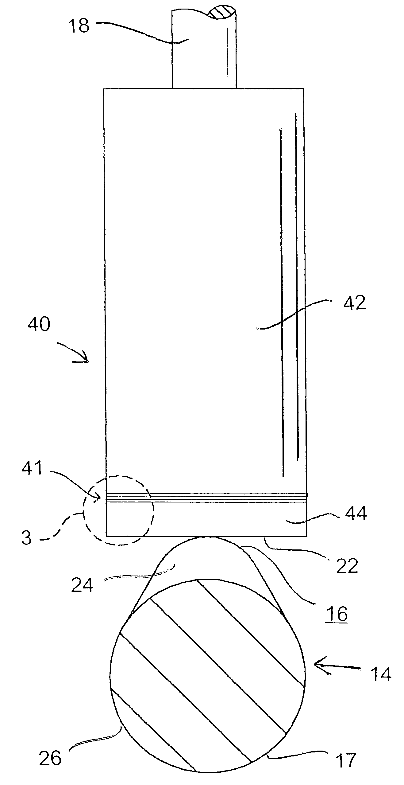
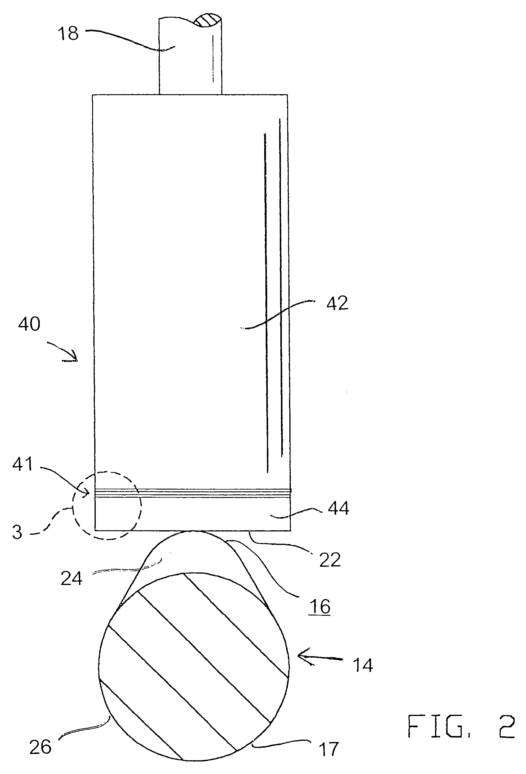
[0029] A lifter according to one embodiment of the invention may be made by the following steps: [0030] 1) Provide a 1⅕ inch diameter, 2¼ inch long body—a cylinder of iron alloy, cut and milled from a long bar of AMS #4771. [0031] 2) Clean body with alcohol, and apply flux to rid of oxygen. [0032] 3) Place silver-copper based wafer in between the body and a metal carbide face pad (for example, as described above), and insert as an assembly into induction unit. [0033] 4) Heat induction weld unit 1370 degrees F., heating up over about 60 seconds, and then shut off after temperature reached. [0034] 5) Let induction unit with welded assembly (lifter) therein cool in ambient conditions. [0035] 6) Remove assembly, descale it with sand blasting, and grind (with diamond stones) both the body and the face pad attached to the body, to desired dimensions. [0036] 7) Grind a crown onto the face pad using diamond stone, the crown preferably being a slight rounding of the face pad, at approximatel...
PUM
 Abstract
Description
Claims
Application Information