Apparatus for valve communication and control

a technology for valves and actuators, applied in the direction of valve operating means/releasing devices, transportation and packaging, service pipe systems, etc., can solve the problems of large additional space and complexity in previous attempts to integrate communication/control and pneumatic valves together

Inactive Publication Date: 2007-02-15
STONEL
View PDF47 Cites 60 Cited by
  • Summary
  • Abstract
  • Description
  • Claims
  • Application Information

AI Technical Summary

Benefits of technology

[0008] The present invention provides a compact, durable, modular communication and control platform which combines position sensing and pneumatic control capabilities into a single, integrated package.

Problems solved by technology

Previous attempts to integrate communication / control and pneumatic valves together have typically required substantial additional space and complexity as compared to standardized automated valve assemblies where the pneumatic valve and valve communication terminal are attached directly and separately to the actuator.

Method used


Image

  • Apparatus for valve communication and control
  • Apparatus for valve communication and control
  • Apparatus for valve communication and control

Examples


Embodiment Construction

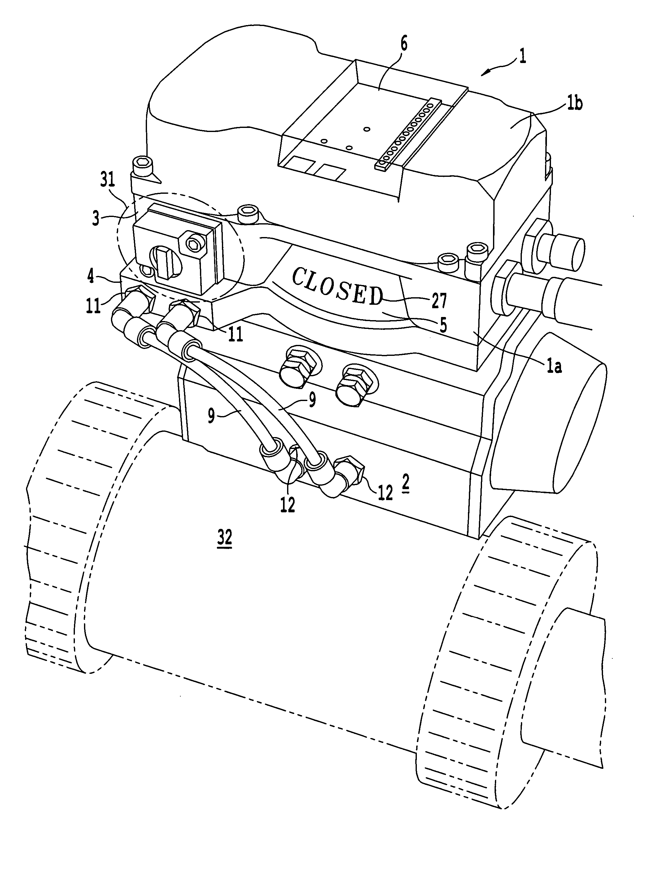
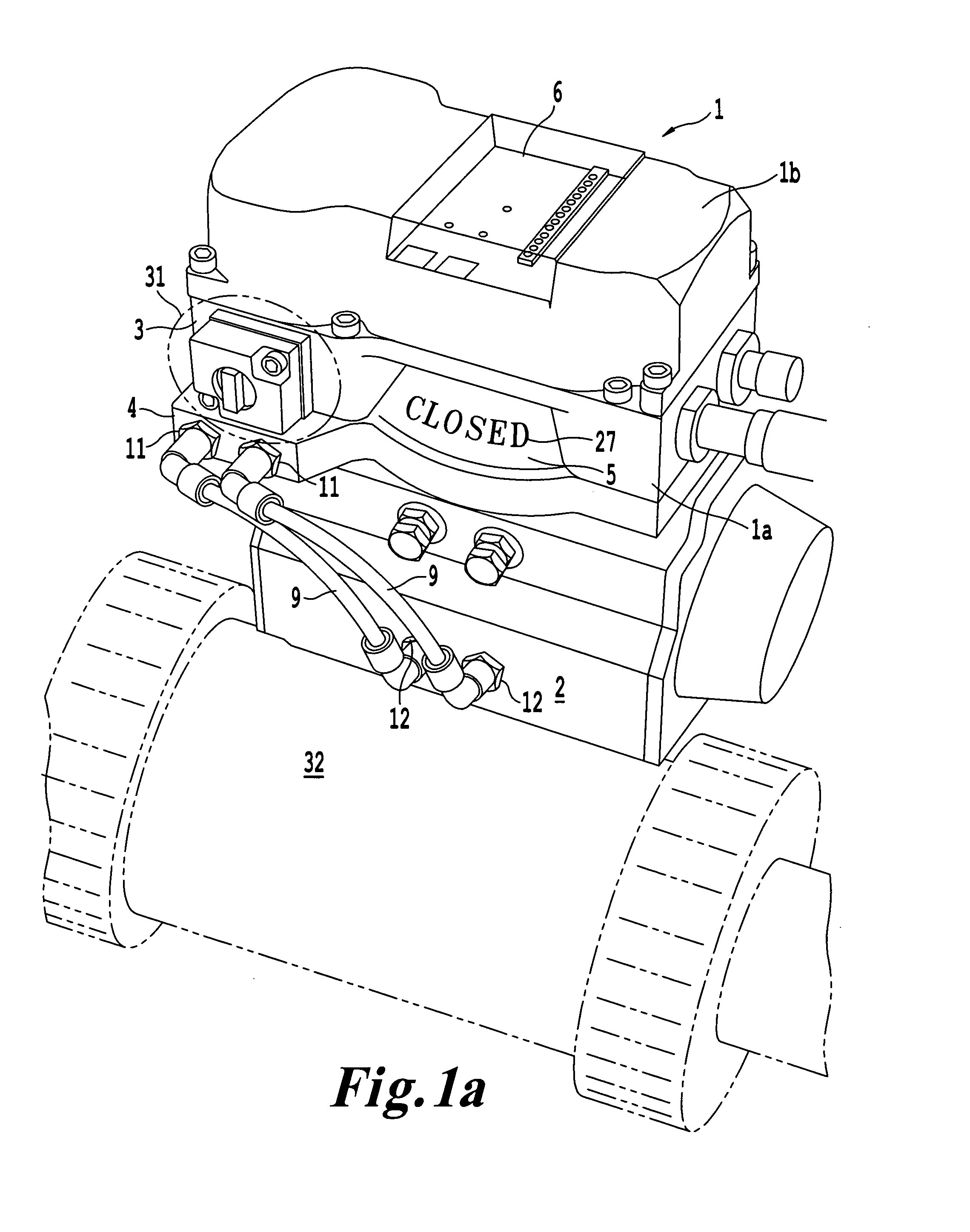
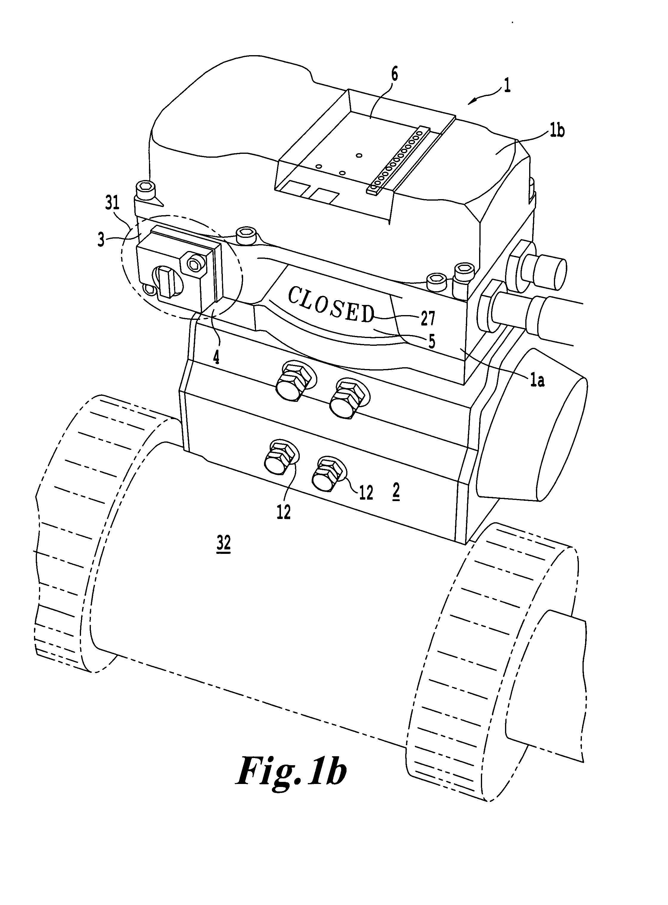
[0036] Referring now to the drawings, wherein like reference numerals designate identical or corresponding parts throughout the several views.

[0037] In the non-limiting example shown in FIGS. 1a, 1b and 2, a communication and control device 1 is attached to a rotary valve actuator 2. The rotary valve actuator is attached to a process valve 32. The control device 1 is typically divided into two main parts, housing cover 1b and main housing 1a. In this particular example, the rotary valve actuator 2 complies with NAMUR accessory design parameters, and the main housing 1a attaches to the rotary valve actuator 2 via a hole pattern in compliance with the NAMUR accessory standard. However, the invention may work with valve actuators that comply with other mounting standards and with valve actuators that do not comply with any standard for mounting accessories.

[0038] The rotary valve actuator 2 typically controls a process valve 32 such as a ball valve or butterfly valve mounted in line ...


PUM


Abstract

A device for controlling a valve rotary actuator and communicating information regarding the valve rotary actuator, including a non-contact sensor which monitors, through a continuous range of rotation, the rotational position of a rotating unit connected to the valve rotary actuator, a main housing including a pneumatic valve body integrally formed with the main housing, the pneumatic valve body accommodating a valve spool, a sensor housing which supports the non-contact sensor and is connected to the main housing, and a manifold including a pathway in fluid communication with the pneumatic valve body.

Description

FIELD OF THE INVENTION [0001] The invention relates to devices for indicating the status and controlling discrete automatic process valves such as, for example, air operated ball and butterfly valves. The devices typically send signals visually and electronically, indicating automatic valve parameters. One such parameter is whether the automatic valve is open or closed. The devices also control the flow of air into the automatic valve actuator which drives the process valve to a predetermined position. BACKGROUND OF THE INVENTION [0002] Automatic valves are used throughout industry when fluid processes are to be controlled by PLCs or other logic devices. The automatic valves typically operate using an electric solenoid and pneumatic actuator or, an electric motor to cause a process valve to block or permit fluid flow inside a pipe. [0003] When pneumatic actuators are used to operate the process valve, another, smaller valve (pilot valve) is often used to supply pressurized gas (usua...

Claims


Application Information

Patent Timeline
Patent Type & Authority Applications(United States)
IPC IPC(8): F16K37/00
CPCF16K31/042F16K37/0041Y10T137/8242
Inventor KUNZ, ROSSKUNZ, DOMINICKUNZ, ROBERTJENSON, ROBERTSTOMMES, WALLACE
Owner STONEL
Why Eureka
Try Eureka