
Lamp with inner capsule

a technology of capsules and lamps, which is applied in the direction of energy-saving incandescent lamps, energy-saving buildings, sustainable buildings, etc., can solve the problems of affecting the quality of the lamp. , to achieve the effect of simple and reliable manufacturing and mounting technology, and reducing the overall length of the lamp

Inactive Publication Date: 2007-02-15
GENERAL ELECTRIC CO
View PDF30 Cites 7 Cited by
  • Summary
  • Abstract
  • Description
  • Claims
  • Application Information

AI Technical Summary

Benefits of technology

[0008] This arrangement provides the required mechanical stiffness of this mount structure. The mounted pair can be strengthened by spot welding, for example at two opposite spots.
[0009] Such pair of lead wires can be arranged in different allocation to the stem and the capsule, thus enabling to find an optimum, simple and reliable manufacturing and mounting technology. The end product is shock-resistant due to the connecting construction. As an addition, the overall length of the lamp can be smaller since the stem and the capsule can be placed very close to each other.

Problems solved by technology

This construction, however, does not allow the capsule to be positioned easily during manufacturing.
If the lead wires are separated to lead-in wires to the capsule and lead-out wires to the stem, the process of positioning them to each other during manufacturing requires a quite complicated technology.
In the known structures, the pinch portion is surrounded by a non-transparent metallic element, which results in a considerable light waste at the pinch portion.
Furthermore, said metallic element has a heat-retaining feature, causing a higher lamp working temperature.
This rise in temperature can cause failure due to an internal oxidation of the usual Molybdenum foil in the pinch portion region, and introduction of harmful thermo-mechanical stress.
Other damaging mechanical stresses can also be induced by the unfitting pinch portion geometry, if the pinch portion is clipped too tightly around.
Very often, this can lead to the detachment of the weld between the lead wires of the insert and the stem.
It is to be noted that the number of metal parts required for manufacturing and also the number of processing steps increase the total costs of the lamp significantly.

Method used


Image

  • Lamp with inner capsule
  • Lamp with inner capsule
  • Lamp with inner capsule

Examples


Embodiment Construction

[0031] Same reference numbers identify same functional elements of different embodiments in the drawings.

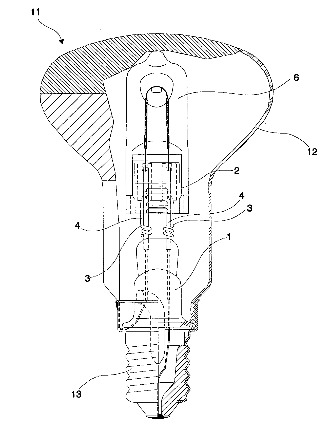
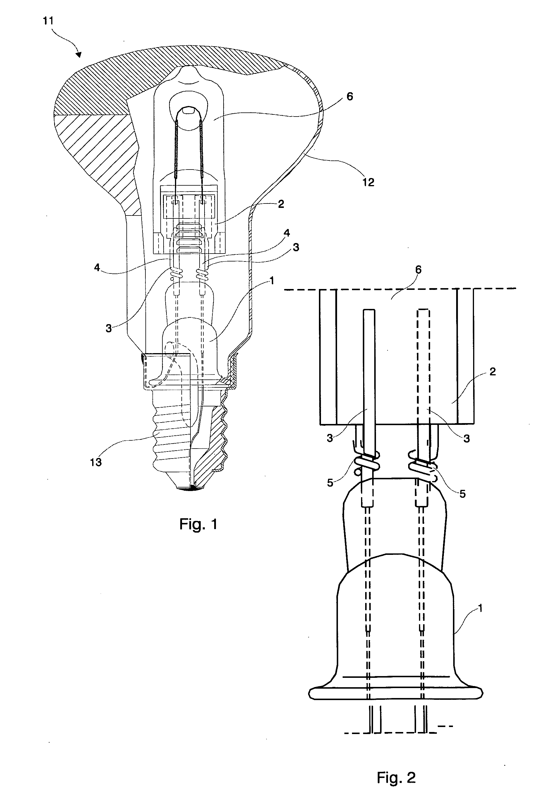
[0032] In FIG. 1, a lamp 11 with an inner capsule 6 having lead wires can be seen. The lamp 11 has an outer envelope 12 with a base 13 at its lower end. A stem 1 is formed at the top of the base 13 in a known way, and made of some glass material. In the mounted state of the lamp 11, the location of the stem 1 is predetermined relative to the outer envelope 12. Lead-out wires 4 protrude out of the stem 1 with one end, while the other end of the lead-out wires 4 provide electrical coupling to the base 13. The inner capsule 6 has a pinch portion 2 and lead-in wires 3 protrude out of the inner capsule 6 in such a manner, that at least relevant parts of them are parallel to the central plane of the pinch portion 2. The lead-in wires 3 and the lead-out wires 4 are connected to each other and constitute pairs of lead wires which have a function to provide mechanical and electrical conn...


PUM


Abstract

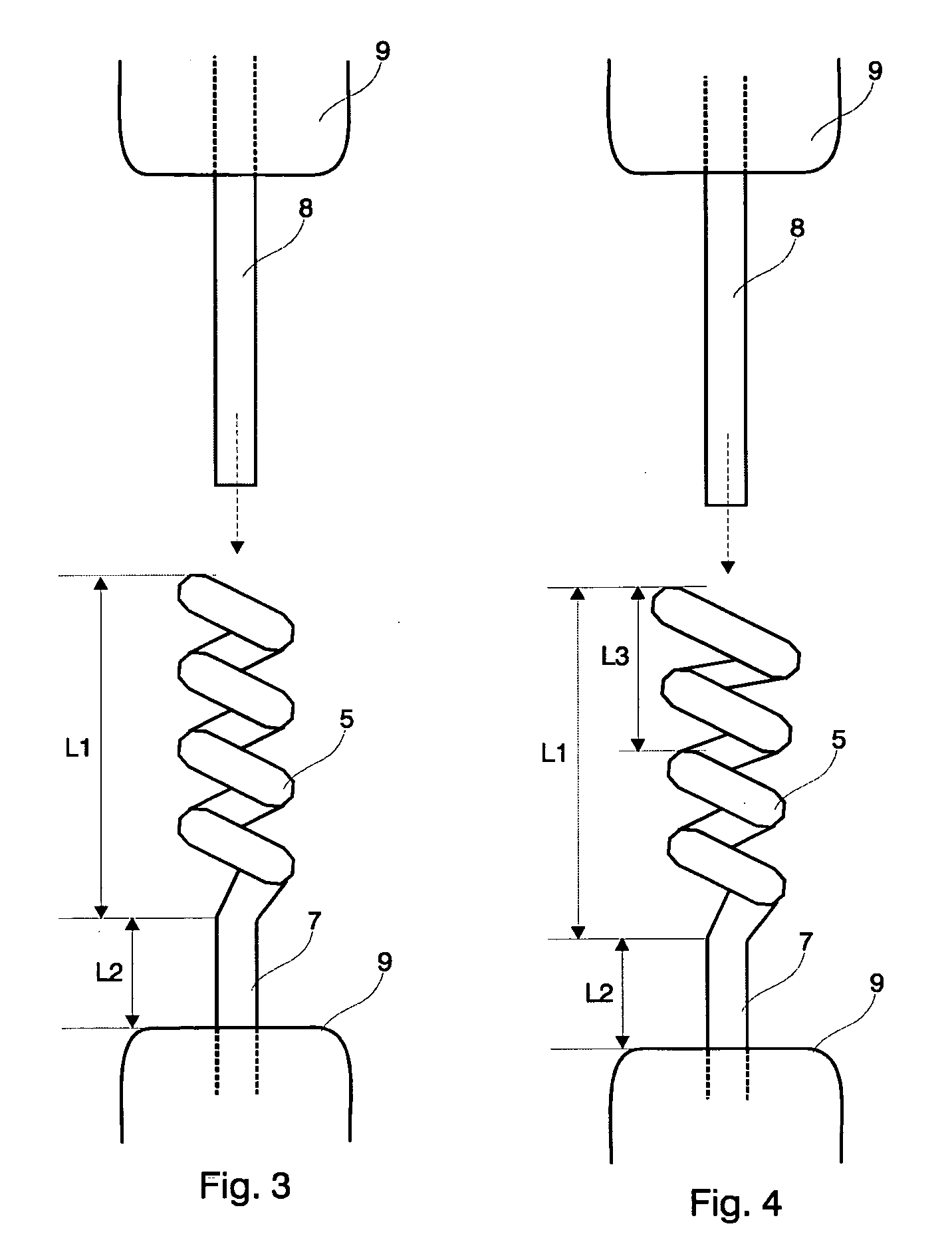
A lamp with an inner capsule having lead wires comprises an outer envelope, a lamp base at the end of the outer envelope, a stem formed at the base in a location predetermined relative to the outer envelope of the lamp, and lead-out wires protruding out of the stem. The inner capsule has a pinch portion and lead-in wires protruding out of the inner capsule at least partially parallel to the central plane of the pinch portion. The lead-in wires and the lead-out wires constitute pairs of lead wires providing mechanical and electrical connection between the stem and the inner capsule. Each pair of lead wires comprises a substantially straight wire of a predetermined diameter and a spooled wire of a spooling core diameter being not smaller than said predetermined diameter, and the pairs are mounted by pushing the straight wire through the core of the spooled wire.

Description

BACKGROUND OF THE INVENTION [0001] This invention relates to a lamp with an inner capsule, more particularly, to an inner capsule connected to a stem of the lamp. [0002] In case of different lamps mounted with inner burner capsule, such as, for example, Haloreflectors, a double envelope structure is formed during manufacturing the lamp. The lamp is provided with a base at the end of the outer envelope, while a stem is formed at the base in a location predetermined relative to the outer envelope. The light-emitting capsule is generally mounted upon a stem being hermetically sealed to the outer envelope. Lead-out wires protrude out of the stem within the sealed space. The inner capsule has a substantially plane pinch portion and lead-in wires are used that protrude out of the inner capsule. [0003] U.S. Pat. No. 4,673,840 discloses a rugged mount structure for supporting a hard glass light-emitting capsule within a soft glass outer envelope. The capsule is mounted upon a soft glass ste...

Claims


Application Information

Patent Timeline
IPC IPC(8): H01J17/18
CPCH01J5/50H01J61/34H01J61/36Y02B20/125H01K1/40H01K1/42H01K1/34Y02B20/00
Inventor CSEH, GEZANAGY, PETER LAJOSFAZEKAS, FERENC
Owner GENERAL ELECTRIC CO
Learn More