System and method for ray tracing with depth buffered display

a buffered display and ray tracing technology, applied in the field of system and method for ray tracing with buffered display, can solve the problems of polygon rendering producing images that may not meet the image quality requirements of users, and ray tracing may not meet user's performance requirements

a buffered display and ray tracing technology, applied in the field of system and method for ray tracing with buffered display, can solve the problems of polygon rendering producing images that may not meet the image quality requirements of users, and ray tracing may not meet user's performance requirements

US20070035544A1Inactive Publication Date: 2007-02-15IBM CORP +2

Image

  • System and method for ray tracing with depth buffered display
  • System and method for ray tracing with depth buffered display
  • System and method for ray tracing with depth buffered display

Examples


Embodiment Construction

[0022] The following is intended to provide a detailed description of an example of the invention and should not be taken to be limiting of the invention itself. Rather, any number of variations may fall within the scope of the invention, which is defined in the claims following the description.

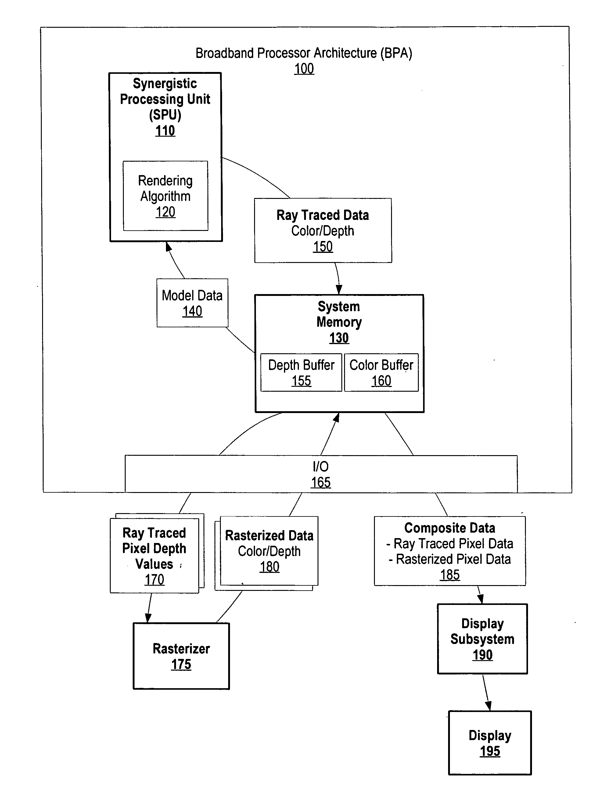
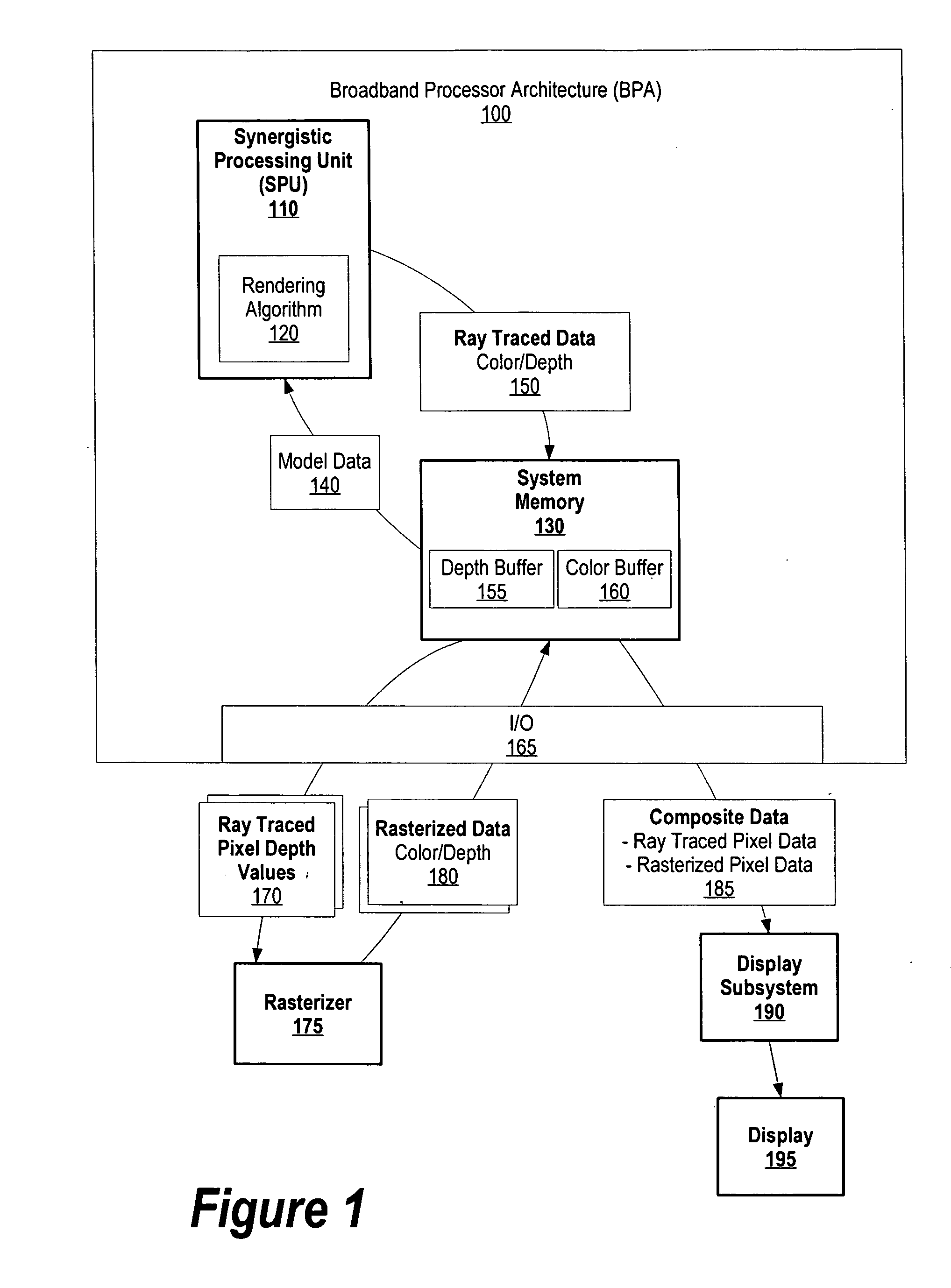
[0023]FIG. 1 is a diagram showing a rasterizer overwriting ray traced pixel data with rasterized pixel data based upon corresponding depth values. Broadband processor architecture 100 includes synergistic processing unit (SPU) 110 and system memory 130. SPU 110 is a processing core, such as a digital signal processor, a microcontroller, a microprocessor, or a combination of these cores. In a preferred embodiment, SPU 110 includes a local memory, registers, four floating point units, and four integer units. As one skilled in the art can appreciate, depending upon the processing power required, SPU 110 may include a greater or lesser number of floating points units and integer units.

[0024] SP...


PUM


Abstract

A system and method for generating an image that includes ray traced pixel data and rasterized pixel data is presented. A synergistic processing unit (SPU) uses a rendering algorithm to generate ray traced data for objects that require high-quality image rendering. The ray traced data is fragmented, whereby each fragment includes a ray traced pixel depth value and a ray traced pixel color value. A rasterizer compares ray traced pixel depth values to corresponding rasterized pixel depth values, and overwrites ray traced pixel data with rasterized pixel data when the corresponding rasterized fragment is “closer” to a viewing point, which results in composite data. A display subsystem uses the resultant composite data to generate an image on a user's display.

Description

BACKGROUND OF THE INVENTION [0001] 1. Technical Field [0002] The present invention relates in general to a system and method for ray tracing with depth buffered display. More particularly, the present invention relates to a system and method for compositing a ray traced image with a rasterized image using a shared depth buffer. [0003] 2. Description of the Related Art [0004] Today's computer image generation technologies produce realistic images in applications such as computer games and flight simulations. The increase of computer system processing speeds is one of the main enablers to generate realistic computer images. A computer image, especially in gaming applications, typically includes many objects that are rendered to generate the image. For example, a gaming application may include objects such as landscaping, mountains, sky, clouds, vehicles and people. [0005] Many approaches are available for generating computer images. Ray tracing is a popular approach to render objects....

Claims


Application Information

Patent Timeline
15 Feb 2007
Publication
US20070035544A1
IPC
G06T15/40; G06T15/06; G06T15/08
CPC
G06T15/06; G06T15/405; G06T15/08
Inventors
FOSSUM, GORDON CLYDE; MINOR, BARRY L.