Demodulation device and demodulation method

a demodulation device and orthogonal frequency division technology, applied in the direction of orthogonal multiplex, synchronisation signal speed/phase control, baseband system details, etc., can solve the problem of increasing noise that is other than desired signals, unable to achieve sufficient noise suppression effect, and unable to reduce the error rate obtained. the effect of demodulation and suppression of unnecessary noise components

Inactive Publication Date: 2007-02-15
MITSUBISHI ELECTRIC CORP
View PDF8 Cites 46 Cited by
  • Summary
  • Abstract
  • Description
  • Claims
  • Application Information

AI Technical Summary

Benefits of technology

[0008] The present invention has been accomplished to resolve the problem such as described above, and its object is to provide a demodulation device and a demodulation method that utilize estimated delay profiles (which refers to information corresponding to the delay wave under multipath environment (delay time, power value, and so fort

Problems solved by technology

For that reason, the pass band of the variable bandwidth filter used for the filtering along the frequency axis may become unnecessarily wide, increasing noise that is other than desired signals.
Accordingly, a problem in th

Method used


Image

  • Demodulation device and demodulation method
  • Demodulation device and demodulation method
  • Demodulation device and demodulation method

Examples


first preferred embodiment

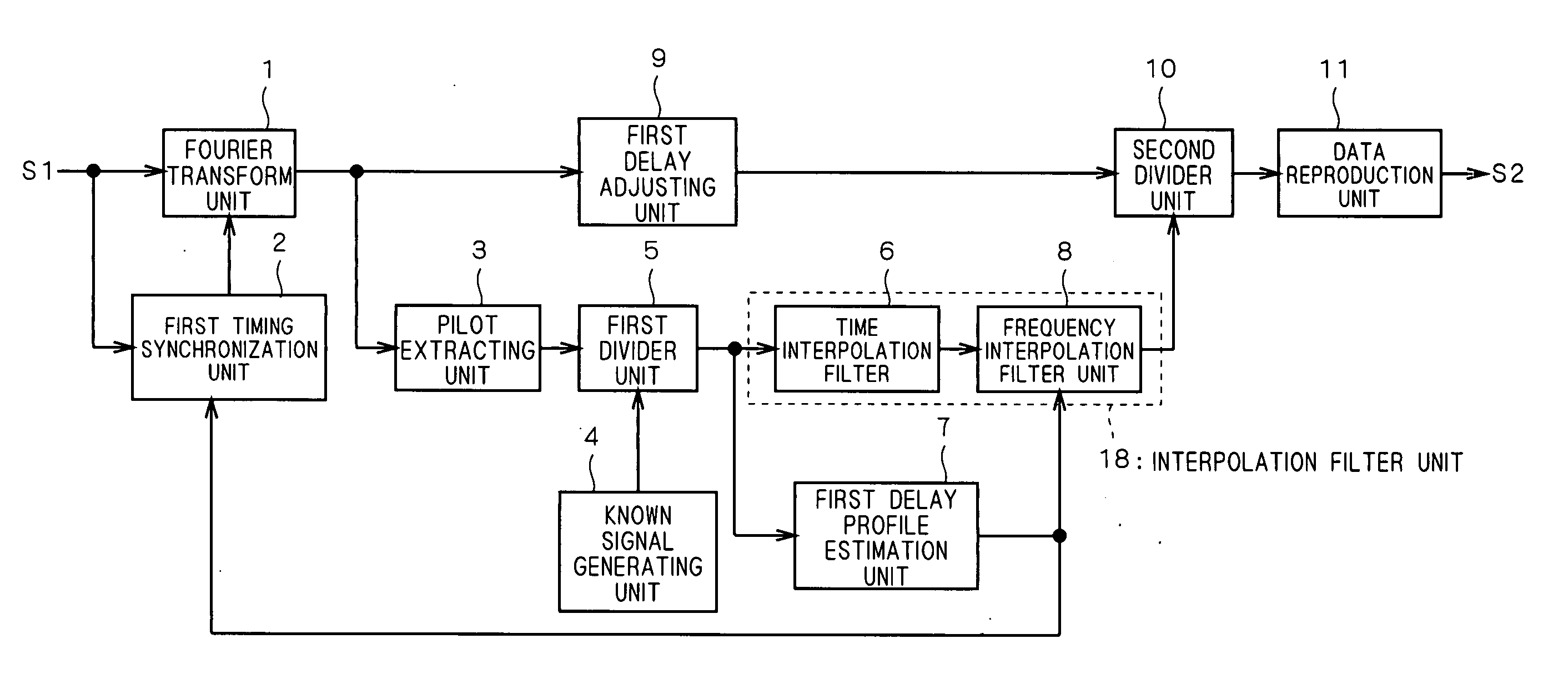
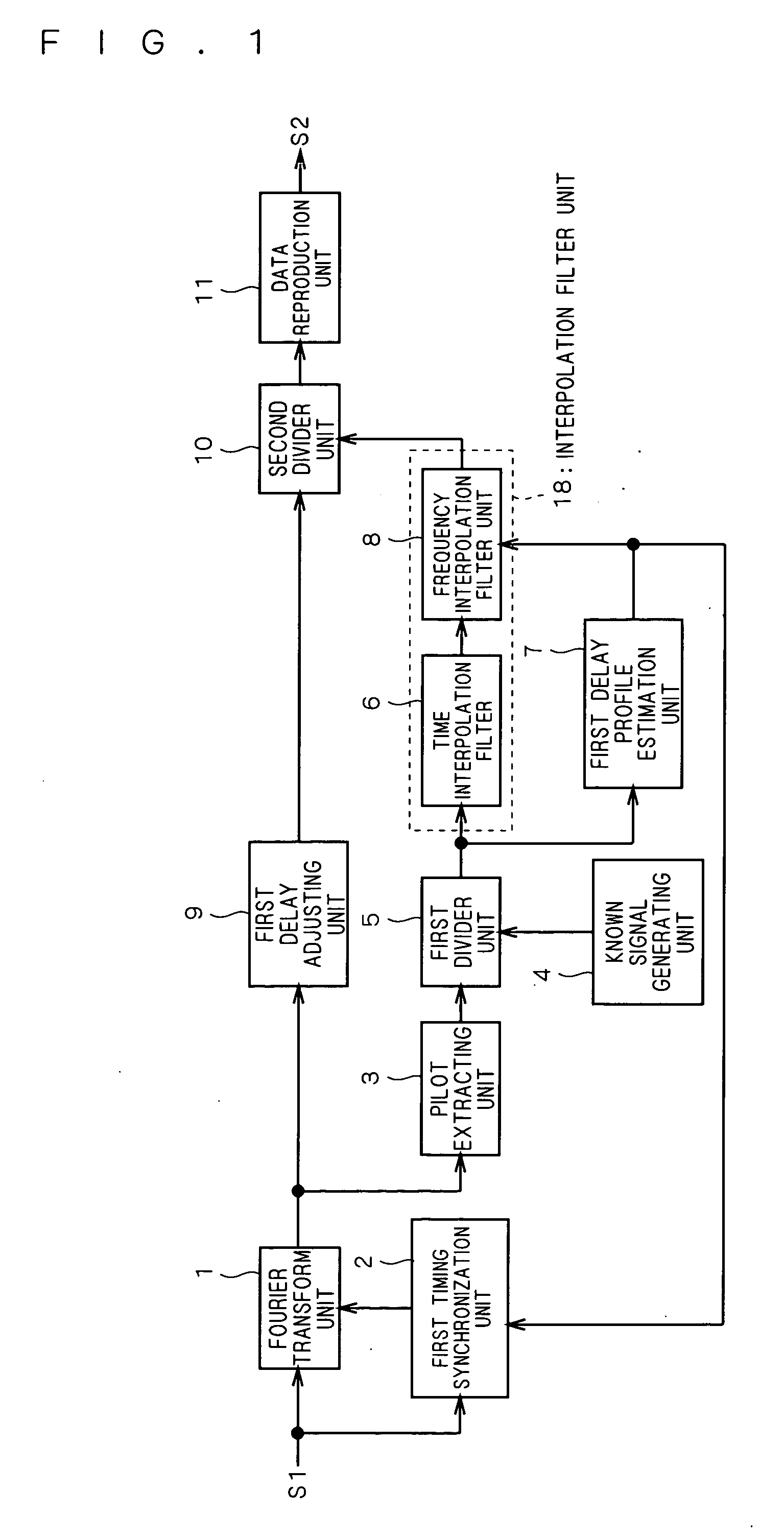
[0029]FIG. 1 is a block diagram showing a configuration example of a demodulation device according to the present preferred embodiment. In FIG. 1, a Fourier transform unit 1 performs a Fourier transform on a signal obtained by frequency-converting a received OFDM signal into a predetermined signal band (the signal is hereinafter also referred to as “S1”) based on a timing signal that is input from a later-described first timing synchronization unit 2, and outputs a subcarrier component contained in S1 to a pilot extracting unit 3 and a first delay adjusting unit 9. The pilot extracting unit 3 extracts a received pilot signal contained in the subcarrier component.

[0030] Since a transmission pilot signal that has been inserted in an OFDM signal with a transmission device is preset in the demodulation device as a known signal, the demodulation device can compute a transmission channel characteristic corresponding to the received pilot signal by comparing the received pilot signal with...

second preferred embodiment

[0057] The demodulation device according to the first preferred embodiment is configured to estimate delay profiles from transmission channel characteristics corresponding to pilot signals that are output from the first divider unit 5; in contrast, the present preferred embodiment is configured to estimate delay profiles based on transmission channel characteristics obtained by interpolating the transmission channel characteristics corresponding to the foregoing pilot signals along the time axis.

[0058]FIG. 7 is a block diagram illustrating the configuration of a demodulation device according to the present preferred embodiment. In FIG. 7, a Fourier transform unit 1, a first timing synchronization unit 2, a pilot extracting unit 3, a known signal generating unit 4, a first divider unit 5, a time interpolation filter unit 6, a frequency interpolation filter unit 8, a first delay adjusting unit 9, a second divider unit 10, and a data reproduction unit 11 have the same configurations a...

third preferred embodiment

[0068] The demodulation devices of the foregoing first and second preferred embodiments are configured to control the frequency axis interpolation filter while adjusting the synchronization timing for performing a Fourier transform. In the present preferred embodiment, a demodulation device is configured to give a phase rotation to a subcarrier component that is output from the Fourier transform unit 1, corresponding to the frequency of the subcarrier component, and also to control the frequency axis interpolation filter.

[0069]FIG. 8 is a block diagram illustrating the configuration of a demodulation device according to the present preferred embodiment. In FIG. 8, a Fourier transform unit 1, a pilot extracting unit 3, a known signal generating unit 4, a first divider unit 5, a time interpolation filter unit 6, a first delay profile estimation unit 7, a frequency interpolation filter unit 8, a second divider unit 10, and a data reproduction unit 11 have the same configurations as th...


PUM


Abstract

The present invention relates to a demodulation device and a demodulation method, and its object is to demodulate subcarrier components utilizing estimated delay profiles to control the timing for performing a Fourier transform and the pass band of an interpolation filter used in interpolating transmission channel characteristics along a frequency axis so as to suppress unnecessary noise components, whereby an error rate after the demodulation is reduced. To achieve the object, in a demodulation device according to the present invention, a Fourier transform unit 1 performs a Fourier transform according to a timing signal and an interpolation filter unit 18 sets a pass band of a frequency interpolation filter used for interpolation along the frequency axis based on a signal corresponding to a maximum delay time, whereby the frequency band of a transmission channel characteristic corresponding to a subcarrier component is restricted when it is output.

Description

TECHNICAL FIELD [0001] The present invention relates to a demodulation device and a demodulation method for orthogonal frequency division multiplex signal (hereinafter also referred to as “OFDM signal”). BACKGROUND OF THE INVENTION [0002] A conventional OFDM signal demodulation device performs demodulation of OFDM signals in the following manner. [0003] Specifically, the demodulation device performs a Fourier transform on a received OFDM signal with a Fourier transform circuit to obtain a Fourier transform signal. It also generates a pilot signal that synchronizes with the Fourier transform signal with a pilot signal generating circuit. [0004] The Fourier transform signal is divided by the pilot signal at a divider, and thereby a transmission channel characteristic corresponding to the pilot signal is computed. Meanwhile, a delay time calculation circuit computes a maximum delay time in delay wave components in the received OFDM signal. A Doppler frequency calculation circuit comput...

Claims


Application Information

Patent Timeline
IPC IPC(8): H04K1/10H04B1/10H04L7/00H04J11/00H04L25/02H04L27/26
CPCH04L5/0048H04L25/0216H04L27/2665H04L25/0234H04L27/2655H04L25/0222
Inventor IDO, JUN
Owner MITSUBISHI ELECTRIC CORP
Why Eureka
Try Eureka