Hollow fan blade for gas turbine engine

a gas turbine engine and fan blade technology, which is applied in the direction of liquid fuel engines, vessel construction, marine propulsion, etc., can solve the problems of metal flexing, buckling of caverns, airfoils bending, etc., and achieves low cross-sectional inertia, improved durability, and minimizing weight and cost.

Inactive Publication Date: 2007-02-15
RAYTHEON TECH CORP
View PDF33 Cites 6 Cited by
  • Summary
  • Abstract
  • Description
  • Claims
  • Application Information

AI Technical Summary

Benefits of technology

[0009] The present invention provides a hollow fan blade with internal cavity and rib geometry with improved durability while minimizing weight and cost. In the present invention, regions of the hollow fan blade that may be loaded in multiple directions, such as the outer half span, feature cavities and ribs that do not run solely spanwise or chordwise, but curve and change direction. As a result, these regions do not form “hinge lines” and long, straight cavities with low cross-sectional inertia are eliminated.
[0010] Rib segments that run roughly perpendicular to each other provide mutual support, with a secondary benefit of minimizing the volume of any fillets where two ribs meet. The thickness of the walls can be reduced because of the improved arrangement of the ribs. This configuration of ribs provides stiffness in multiple directions while minimizing the cost and complexity of the manufacturing process by using primarily continuous cavities to form the ribs.

Problems solved by technology

When the fan blades encounter large loading, the cavities are susceptible to buckling when the loads are applied in a direction perpendicular to the ribs.
Outer spans typically are subject to loads from bird (or other foreign object) impact, which applies a heavy initial load at the leading edge, tending to cause bending of the airfoil at the leading edge.
But there are secondary loads milliseconds after the impact, causing a shock wave that radiates out from the impact site, which flexes the metal as it passes the loads onward.
Blade tips are also subject to occasional circumferential loading when blades rub the case during heavy crosswinds or maneuver loading, or in a severe case, during a blade out event.
For tip rubs, chordwise cavities tend to be prone to buckling.

Method used


Image

  • Hollow fan blade for gas turbine engine
  • Hollow fan blade for gas turbine engine
  • Hollow fan blade for gas turbine engine

Examples


Embodiment Construction

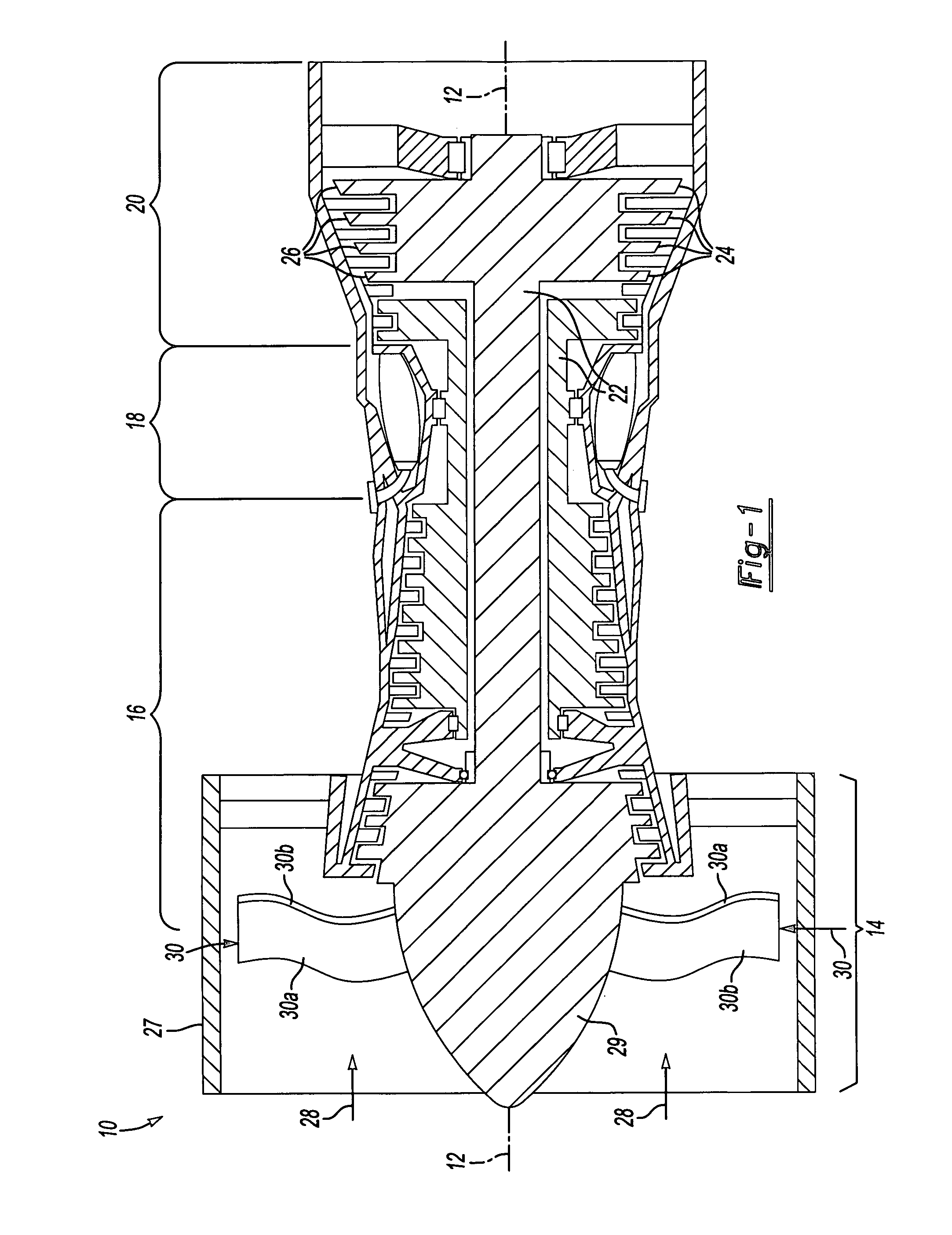
[0016] A gas turbine engine 10, such as a turbofan gas turbine engine, circumferentially disposed about an engine centerline, or axial centerline axis 12 is shown. The engine 10 includes a fan 14, a compressor 16, a combustion section 18 and a turbine 20. As is well known in the art, air compressed in the compressor 16 is mixed with fuel, which is burned in the combustion section 18 and expanded in turbine 20. The air compressed in the compressor and the fuel mixture expanded in the turbine 20 can both be referred to as a hot gas stream flow 28. The turbine 20 includes rotors 22 that rotate in response to the expansion, driving the compressor 16 and fan 14. The turbine 20 comprises alternating rows of rotary airfoils or blades 24 and static airfoils or vanes 26.

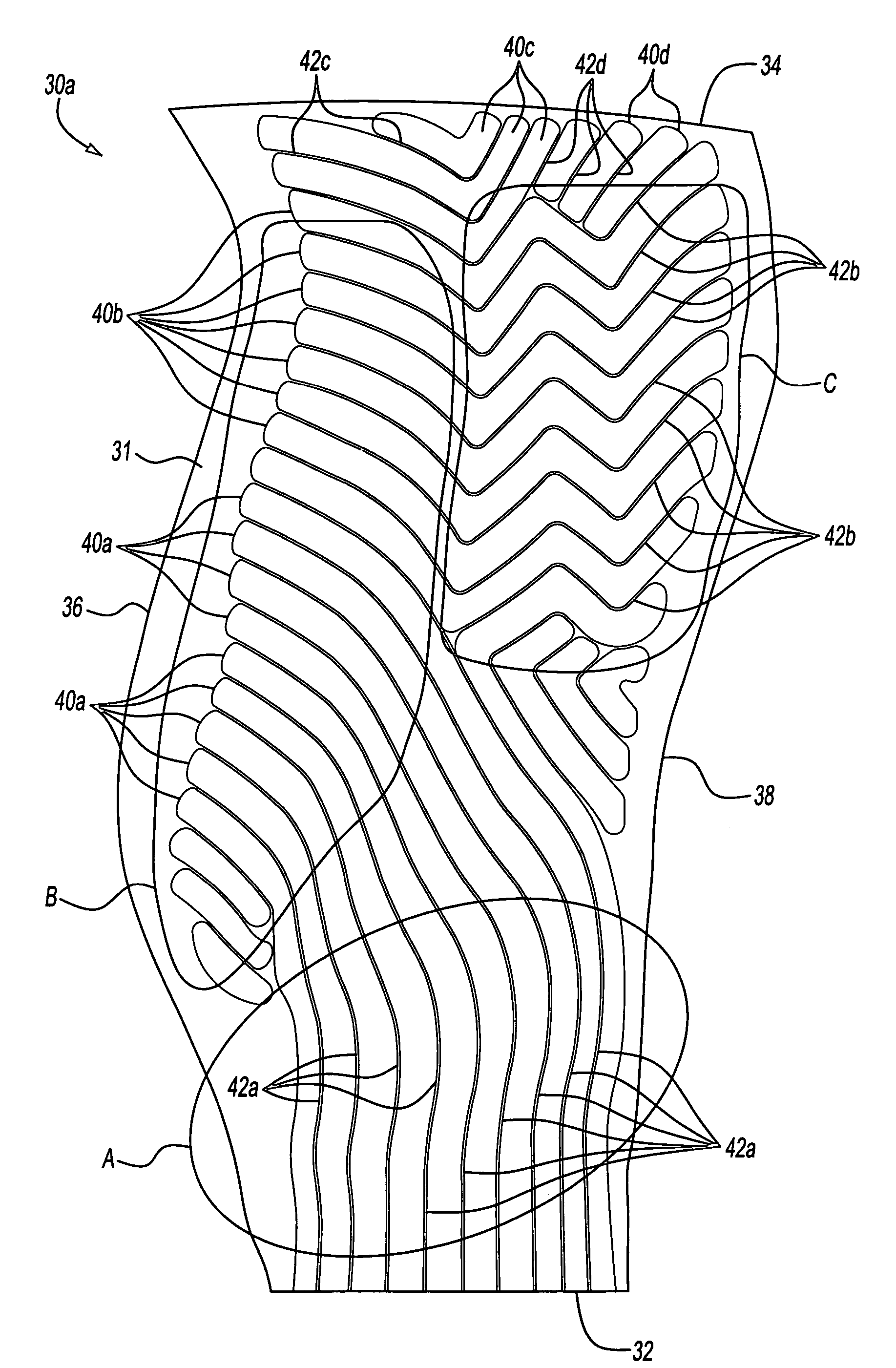
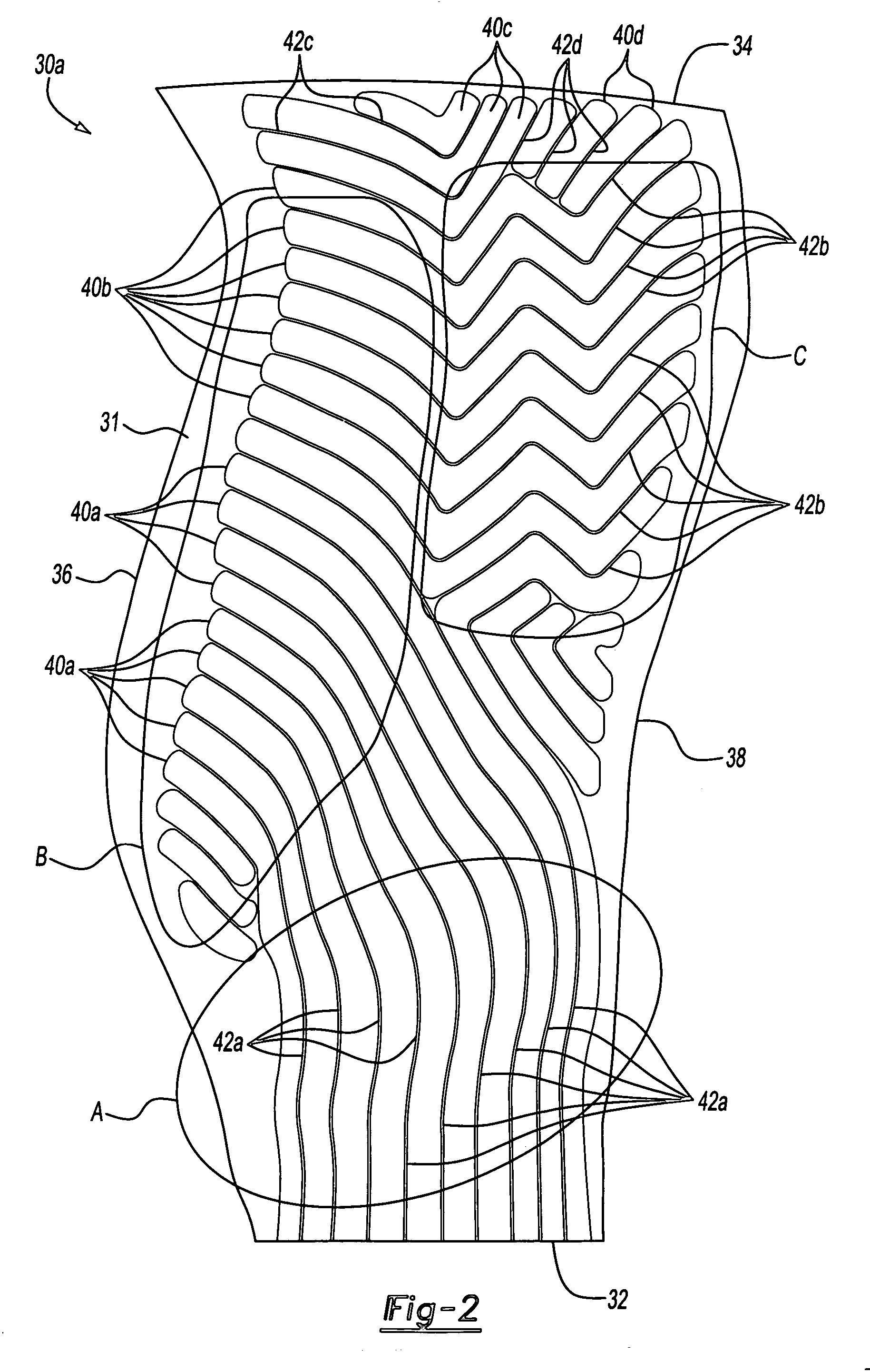
[0017] The fan 14 is surrounded by a fan case 27 and includes a rotor assembly. The rotor assembly includes a rotor disk 29 and a plurality of fan blades 30. Each fan blade 30 extends radially outwardly from the rotor disk 2...


PUM

PropertyMeasurementUnit
angleaaaaaaaaaa
angleaaaaaaaaaa
acute angleaaaaaaaaaa

Abstract

Hollow fan blades for turbo fan gas turbine engines are formed of two separate detail halves. Each detail half has a plurality of cavities machined out to reduce weight and form ribs. The ribs extend continuously and without intersecting one another in order to facilitate machining. The ribs extend in different directions in different regions of the detail half. In at least one region, the ribs extend in a serpentine pattern, such that concatenated rib segments are substantially perpendicular to one another, thereby providing stiffness in multiple directions.

Description

BACKGROUND OF THE INVENTION [0001] The present invention relates generally to gas turbine engines and more particularly to an improved hollow fan blade for a gas turbine engine. [0002] A gas turbine engine, such as a turbo fan engine for an aircraft, includes a fan section, a compression section, a combustion section and a turbine section. An axis of the engine is centrally disposed within the engine and extends longitudinally through the sections. The primary flow path for working medium gases extends axially through the sections of the engine. A secondary flow path for working medium gases extends parallel to and radially outward of the primary flow path. [0003] The fan section includes a rotor assembly and a stator assembly. The rotor assembly of the fan includes a rotor disc and plurality of radially extending fan blades. The fan blades extend through the flow path and interact with the working medium gases and transfer energy between the fan blades and working medium gases. The...

Claims


Application Information

Patent Timeline
Patent Type & Authority Applications(United States)
IPC IPC(8): F01D5/18
CPCB23P15/04F01D5/147F01D5/18F04D29/324F05D2230/10Y02T50/671Y02T50/676F05D2220/36F05D2250/185Y02T50/60
Inventor WEISSE, MICHAEL A.GRAVES, WILLIAM R.
Owner RAYTHEON TECH CORP
Why Eureka
Try Eureka