Controlling an I/O MMU

a memory management unit and mmu technology, applied in computing, instruments, data conversion, etc., can solve the problems of reducing i/o systems are not designed, and the use of physical addresses by devices reduces the overall security of the system

Active Publication Date: 2007-02-15
MEDIATEK INC
View PDF8 Cites 41 Cited by
  • Summary
  • Abstract
  • Description
  • Claims
  • Application Information

AI Technical Summary

Benefits of technology

[0008] In one embodiment, a method comprises creating a command queue in a memory of a computer system that also includes an input/output memory management unit (IOMMU). The IOMMU is configured to implement address translation and memory protection for memory requests sourced by one or more input/output (I/O) devices in the system. The method comprises writing one or more control commands to the command queue by a memory management module executable on a processor in the computer system. The method still further comprises the IOMMU reading the control commands from the command queue and executing the commands.
[0009] In an embodiment, a computer system comprises a processor; a memory management module comprising a plurality of instructions executable on the processor; a memory coupled to the processor; and an IOMMU coupled to the memory. The IOMMU is

Problems solved by technology

However, such mechanisms become more complicated and cumbersome in virtual machine systems, which may have multiple guest OSs running on a virtual machine monitor.
Additionally, devices' use of physical addresses reduces the ove

Method used


Image

  • Controlling an I/O MMU
  • Controlling an I/O MMU
  • Controlling an I/O MMU

Examples


Embodiment Construction

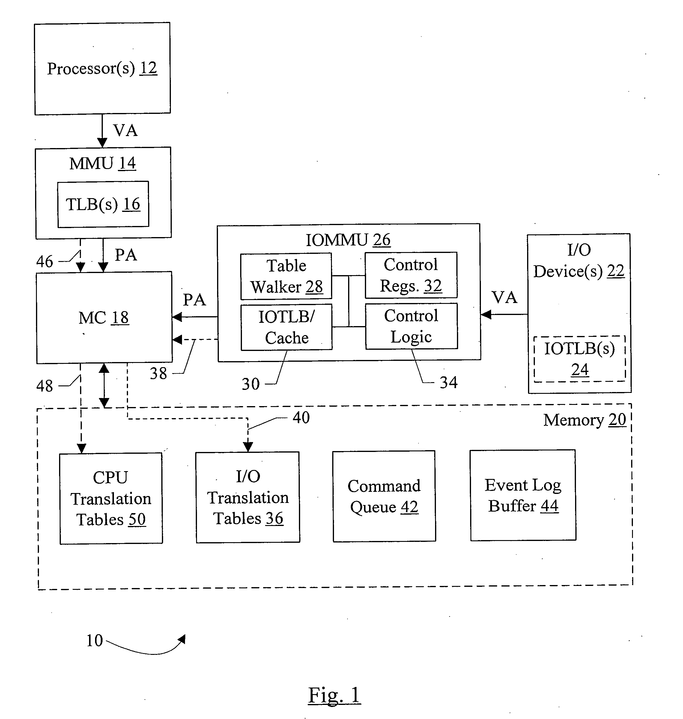
[0023]FIG. 1 is a block diagram illustrating a simplified, high level view of one embodiment of a computer system 10. In the illustrated embodiment, the system 10 includes one or more processors 12, a memory management unit 14 comprising one or more translation lookaside buffers (TLBs) 16, a memory controller (MC) 18, a memory 20, one or more I / O devices 22 which may comprise one or more I / O TLBs (IOTLBs) 24, and an I / O MMU (IOMMU) 26 which may comprise a table walker 28, an IOTLB / cache 30, control registers 32, and control logic 34. The processors 12 are coupled to the MMU 14, which is coupled to the memory controller 18. The I / O devices 22 are coupled to the IOMMU 26, which is coupled to the memory controller 18. Within the IOMMU 26, the table walker 28, the IOTLB 30, the control registers 32, and the control unit 34 are coupled.

[0024] As illustrated in FIG. 1, the path from the I / O devices 22 to the memory 20 is at least partially separate from the path of the processors 12 to t...


PUM


Abstract

In an embodiment, a computer system comprises a processor; a memory management module comprising a plurality of instructions executable on the processor; a memory coupled to the processor; and an input/output memory management unit (IOMMU) coupled to the memory. The IOMMU is configured to implement address translation and memory protection for memory operations sourced by one or more input/output (I/O) devices. The memory stores a command queue during use. The memory management module is configured to write one or more control commands to the command queue, and the IOMMU is configured to read the control commands from the command queue and execute the control commands.

Description

[0001] This application claims benefit of priority to U.S. Provisional Patent Application Ser. No. 60 / 707,629 filed Aug. 12, 2005. This application also claims benefit of priority to U.S. Provisional Patent Application Ser. No. 60 / 759,826 filed Jan. 17, 2006. The above provisional applications are incorporated herein by reference. To the extent that any material in the provisional applications conflicts with material expressly set forth herein, the material herein controls.BACKGROUND [0002] 1. Field of the Invention [0003] This invention is related to the field of computer systems and, more particularly, to memory management units for input / output (I / O) devices. [0004] 2. Description of the Related Art [0005] Computer systems of various types are ubiquitous in modem society, including personal computers (PCs), workstations, servers, various personal digital assistant (PDA) devices, etc. Most, if not all, of these computer systems have implemented memory management functionality for ...

Claims


Application Information

Patent Timeline
IPC IPC(8): G06F12/00
CPCG06F12/1027G06F12/145G06F12/1081
Inventor HUMMEL, MARK D.LUECK, ANDREW W.STRONGIN, GEOFFREY S.ALSUP, MITCHELLHAERTEL, MICHAEL J.
Owner MEDIATEK INC
Why Eureka
Try Eureka