Rotary pulse type filter dust collector

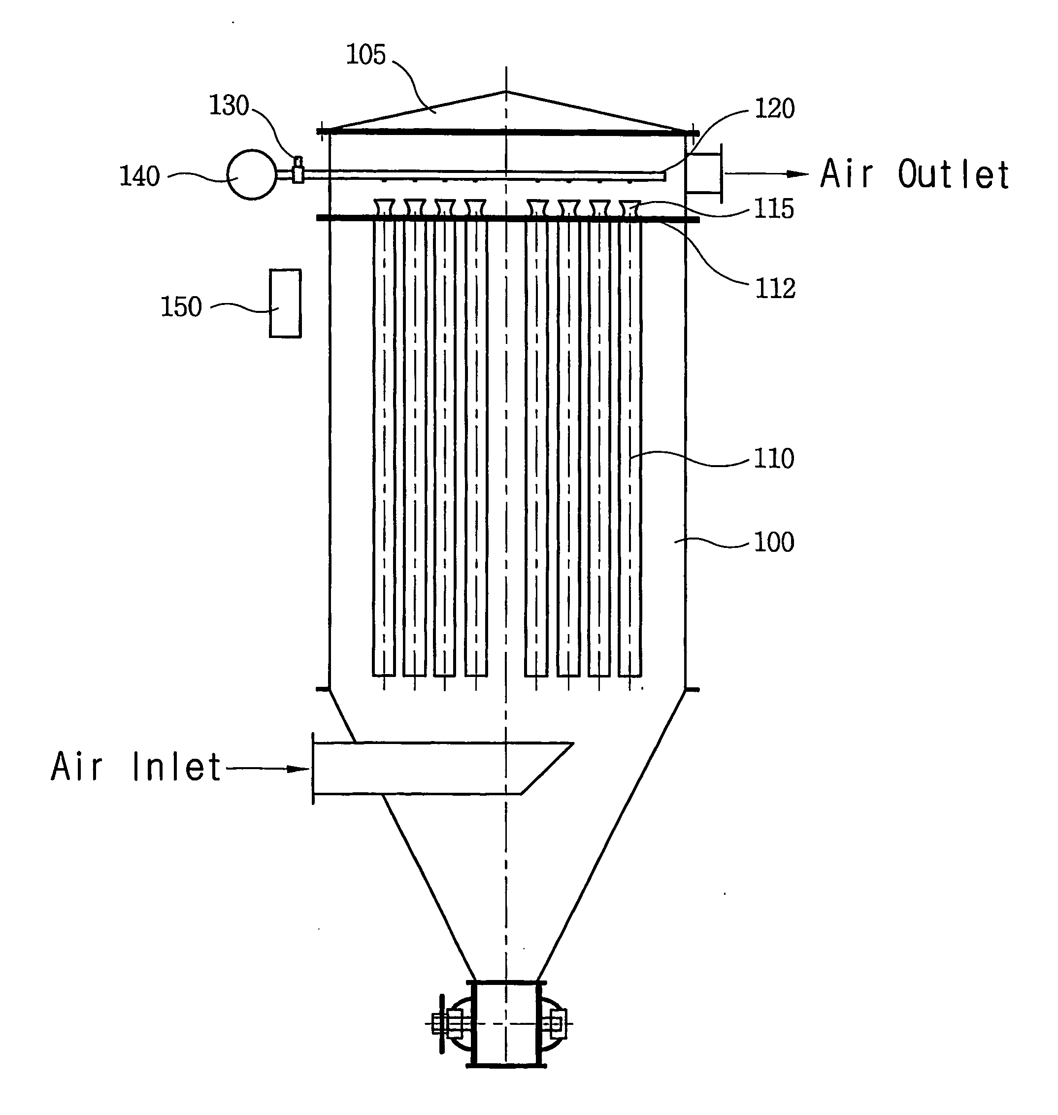
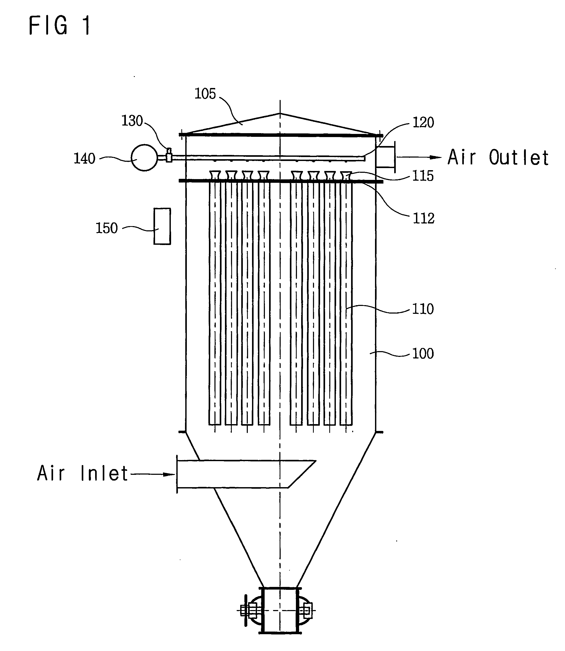
a technology of rotary pulse and dust collector, which is applied in the direction of auxillary pretreatment, separation process, filtration separation, etc., can solve the problems of insufficient cleaning effect, fast blockage of filter bags b>110/b>, and insufficient cleaning effect of conventional dust collectors, so as to reduce manufacturing costs and maintenance fees, improve reliability, and improve efficiency

Inactive Publication Date: 2007-02-22
LEE IN OK
View PDF4 Cites 39 Cited by
  • Summary
  • Abstract
  • Description
  • Claims
  • Application Information

AI Technical Summary

Benefits of technology

[0009] To solve the above problems, the inventor of the present invention has a dust collector, which provides efficiency more excellent than the dust collector of FIG. 1, which is simpler than the low pressure air dust collector of FIG. 2, thereby considerably reducing manufacturing costs and maintenance fees and increasing reliability by reducing troublesome factors to break down.

Problems solved by technology

The dust collector shown in FIG. 1 usually uses high-pressure compressed air of 5˜6 kgf / cm2 as pulse air, but cleaning effect is not sufficient due to weak pulse.
Moreover, the conventional dust collector has a disadvantage in that the filter bags 110 are quickly blocked since condensed water and oil are mixed with the high-pressure compressed air used for generating pulse.
However, the conventional low pressure pulse type dust collector has several disadvantages in that it requires a lot of very expensive components and increases manufacturing costs and maintenance fees because it needs one nozzle and one diaphragm valve for each filter bag and the plurality of solenoid valves (not shown, and ⅓˜¼ of the number of the filter bags 210) are needed to generate a pulse by group of three or four diaphragm valves 270, the timer (or time kit, not shown) to send signal to the solenoid valves to control pulsing interval must be mounted.

Method used


Image

  • Rotary pulse type filter dust collector
  • Rotary pulse type filter dust collector
  • Rotary pulse type filter dust collector

Examples


embodiment 1

[0029] FIGS. 3 to 8 are a first preferred embodiment of the present invention, and show a rounded dust collector body 10. In the first preferred embodiment, diaphragm valves 65 and nozzles 63 are mounted on a fan-shaped compressed air tank 40. When the diaphragm valves 65 and the nozzles 63 arrive at the corresponding filter bags 30 while the compressed air tank 40 is rotating, mechanical 3-way valves 67 instead of electric solenoid valves are used to generate pulses.

[0030] For example, in case of a conventional dust collector with 60 filter bags 30, the conventional dust collector requires 60 nozzles 63 and 60 diaphragm valves 65 for the 60 filter bags 30, but the present invention can be operated only by 10 nozzles 63 and 10 diaphragm valves 65, which are ⅙ of the number of the nozzles and diaphragm valves mounted on the conventional dust collector.

[0031] Furthermore, the present invention adopts simplified mechanical 3-way valves 76 instead of 20 electric solenoid valves, and a...

embodiment 2

[0054] FIGS. 10 to 12 show a second preferred embodiment of the present invention, which is rectangular-shaped dust collector body 10. In the second preferred embodiment of the present invention, as the dust collector is in a rectangular-shape, for example, if 8 filter bags 30 are arranged in 8 rows, long rectangular-shaped compressed air tank 40 having 8 pairs of nozzles 63 and diaphragm valves 65 reciprocates above the filter bags 30. At this time, the compressed air tank 40 pulses and cleans four filter bags 30 eight times on an “A” part when passing above the filter bags 30, and pulses and cleans four filter bags 30 eight times on a “B” part when returning to its original position.

[0055] By repeating the above process, the compressed air tank 40 can clean all of the 64 filter bags 30. At this time, the dust collector according to the present invention uses eight pairs of nozzles 63 and diaphragm valves 65 instead of 64 pairs of nozzles 63 and diaphragms 65, two mechanical 3-way...


PUM

PropertyMeasurementUnit
pressureaaaaaaaaaa
pressureaaaaaaaaaa
rotational speedaaaaaaaaaa

Abstract

The present invention discloses a rotary pulse type filter dust collector, which can maintain excellent de-dusting efficiency of a low pressure pulse type filter dust collector, reduce the number of required components in order to reduce manufacturing costs, maintenance fees, and lower defect factors to provide higher reliability. The dust collector includes: a dust collector body, a number of filter bags, a moving compressed air tank, nozzles, diaphragm valves, mechanical 3-way valves, protrusions, a reduction motor and a mechanical device for driving the compressed air tank, and an inverter controller.

Description

TECHNICAL FIELD [0001] The present invention relates to an industrial filter dust collector, and more particularly, to a rotary pulse type filter dust collector (hereinafter, referred to as ‘rotary pulse type dust collector’), which can maintain excellent de-dusting efficiency of a low pressure pulse type filter dust collector using the air of low pressure (0.5 kgf / cm2) for pulse, reduce the number of required components in order to reduce manufacturing costs and maintenance fees, and lower defect factors to improve reliability. BACKGROUND ART [0002] In general, filter dust collectors are installed on equipments, such as a boiler and an incinerator, which generate dust, installed inside a flour mill, a feed manufacturing factory, a cement manufacturing factory, or the likes. The installed filter dust collectors collect particle type materials such as dust, unburned carbon, and the likes, and remove or recover the collected particles. [0003] For instance, as shown in FIG. 1, a conven...

Claims


Application Information

Patent Timeline
Patent Type & Authority Applications(United States)
IPC IPC(8): B01D46/04B01D46/00B01D46/02
CPCB01D46/0058B01D46/0069B01D46/02B01D46/90B01D46/715
Inventor LEE, CHANG UN
Owner LEE IN OK
Why Eureka
Try Eureka