
Reverse bump test for closed-loop identification of CD controller alignment

a technology of closed loop identification and cd controller, which is applied in the direction of drying machines, lighting and heating apparatus, instruments, etc., can solve the problems of non-uniform cd profiles, non-uniform pulp stock distribution, and common cases

Active Publication Date: 2007-02-22
HONEYWELL ASCA INC
View PDF28 Cites 17 Cited by
  • Summary
  • Abstract
  • Description
  • Claims
  • Application Information

AI Technical Summary

Benefits of technology

[0017] The present invention provides a novel method for identifying the alignment of a sheetmaking system while the system remains in closed-loop control. In contrast to the standard model identification techniques that are employed in conjunction with an open or closed-loop control system, the invention exploits the closed-loop control to its advantage. The technique can include the following steps: (1) leaving the control system in closed-loop, (2) artificially inserting a step signal on top of the measurement profile from the scanner (equivalently, inserting a step signal on top of a setpoint target profile), (3) recording the data as the control system moves the actuators to remove the perceived disturbance, and (4) refining or developing a model from the artificial measurement disturbance to the actuator profile.

Problems solved by technology

Preferably, the cross-directional dry weight profile of the final paper product is flat, that is, the product exhibits no CD variation, however, this is seldom the case.
Various factors contribute to the non-uniform CD profiles such as non-uniformities in pulp stock distribution, drainage, drying and mechanical forces on the sheet.
The causes of these factors include, for example, (i) non-uniform headbox delivery, (ii) clogging of the plastic mesh fabric of the wire, (iii) varying amounts of tension on the wire, (iv) uneven vacuum distribution, (v) uneven press or calendar nip pressures, and (vi) uneven temperatures and airflows across the CD that lead to moisture non-uniformities.
In practice, it is difficult to control sheetmaking machines by adjusting actuators using measurement signals provided by scanning sensors.
The difficulties particularly arise because the scanning sensors are separated from the control actuators by substantial distances in the machine direction.
Because of such separations, it is difficult to determine which measurements zones are associated with which actuator zones.
Such difficulties are referred to as alignment problems in the papermaking art.
Alignment problems are exacerbated when, as is typical, there is uneven paper shrinkage of a paper web as it progresses through a papermaking process.
Another difficulty is that the effect of each actuator is not always limited within the corresponding control zone but spans over a few control zones.
The alignment can change over time and subsequently degrade the controller performance and thus paper quality.
The dye streams initially form parallel lines that extend in the machine direction, but those lines may deviate from parallel if there is web shrinkage during the papermaking process.
Conventional dye tests, however, have numerous drawbacks.
The most serious drawback is that the tests destroy finished product and, therefore, it is seldom feasible to perform dye tests at an intermediate point in a sheetmaking production run, even though sheetmaking processes are likely to drift out of control during such times. Further, because of the limited thickness and high absorption characteristics of tissue grades of paper, dye tests are typically limited to paper products that have relatively high weight grades.
Moreover, model identification for a system in closed-loop control is well known to be challenging.
This is due in part to the fundamental reason that a closed-loop control system works to eliminate any perturbations, so prior art techniques have endeavored to “sneak” a perturbation into the actuator profile that works against the rest of the system and attaining sufficient excitation of the system is difficult to achieve.

Method used


Image

  • Reverse bump test for closed-loop identification of CD controller alignment
  • Reverse bump test for closed-loop identification of CD controller alignment
  • Reverse bump test for closed-loop identification of CD controller alignment

Examples


Embodiment Construction

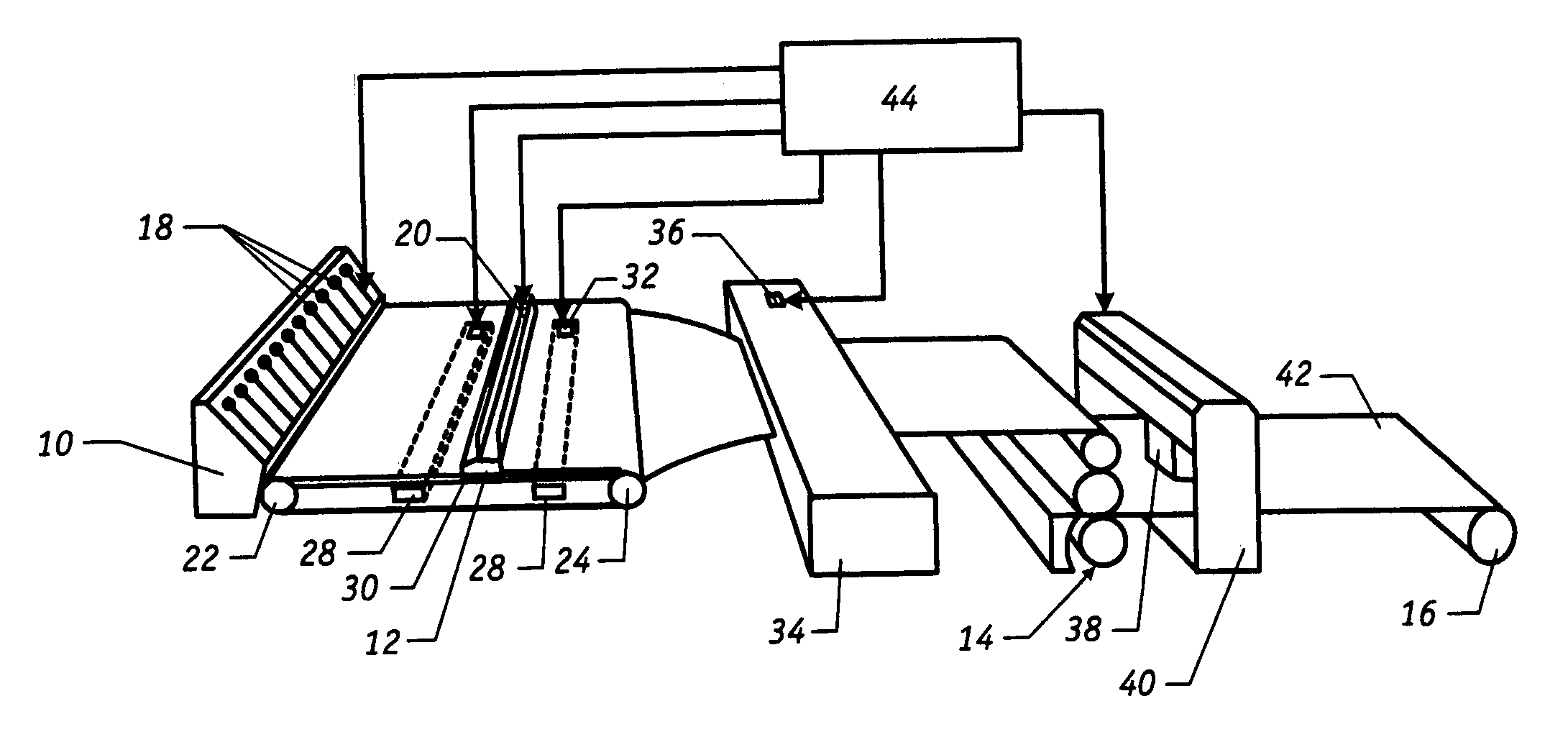
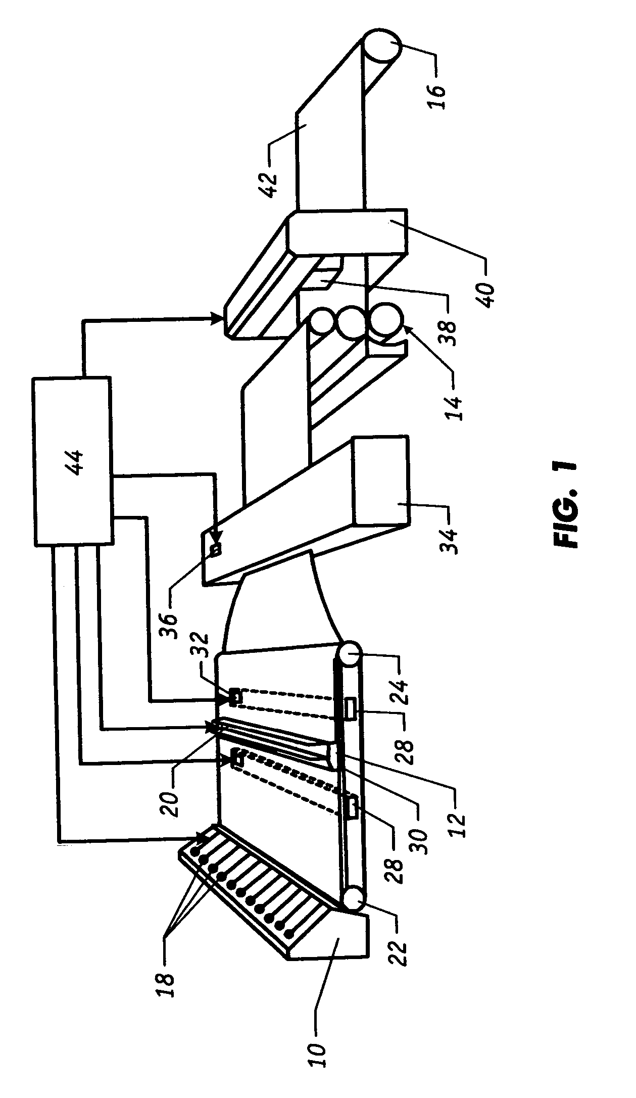
[0045] As shown in FIG. 1, a system for producing continuous sheet material includes various processing stages such as headbox 10, steambox 12, a calendaring stack 14 and reel 16. The array of actuators 18 in headbox 10 controls the discharge of wet stock (or feedstock) material through a plurality of slices onto supporting web or wire 30 which rotates between rollers 22 and 24. Similarly, actuators 20 on steambox 12 can control the amount of steam that is injected at points across the moving sheet. Sheet material exiting the wire 30 passes through a dryer 34 which includes actuators 36 that can vary the cross directional temperature of the dryer. A scanning sensor 38, which is supported on supporting frame 40, continuously traverses and measures properties of the finished sheet in the cross direction. Scanning sensors are known in the art and are described, for example, in U.S. Pat. No. 5,094,535 to Dalquist, U.S. Pat. No. 4,879,471 to Dalquist, et al, U.S. Pat. No. 5,315,124 to Go...


PUM


Abstract

A reverse bump test, for identifying the alignment of a sheetmaking system while the system remains in closed-loop control, includes the following steps: (a) leaving the control system in closed-loop, (b) artificially inserting a step signal on top of the measurement (or setpoint) profile from the scanner, (c) recording the data as the control system moves the actuators to remove the perceived disturbance (or setpoint change), and (d) refining or developing a model from the artificial measurement disturbance (or setpoint change) to the actuator profile. The technique supplies the probing / perturbation signal to the scanner measurement, which is equivalent to supplying the probing / perturbation signal to the setpoint target) rather than inserting bumps via the actuator set points as has been practiced traditionally.

Description

FIELD OF THE INVENTION [0001] The present invention generally relates to techniques for monitoring and controlling continuous sheetmaking systems such as a papermaking machine and more, specifically to maintaining proper cross-directional alignment in sheetmaking systems by extracting alignment information from a closed-loop CD control system. BACKGROUND OF THE INVENTION [0002] In the art of making paper with modern high-speed machines, sheet properties must be continually monitored and controlled to assure sheet quality and to minimize the amount of finished product that is rejected when there is an upset in the manufacturing process. The sheet variables that are most often measured include basis weight, moisture content, and caliper (i.e., thickness) of the sheets at various stages in the manufacturing process. These process variables are typically controlled by, for example, adjusting the feedstock supply rate at the beginning of the process, regulating the amount of steam applie...

Claims


Application Information

Patent Timeline
Patent Type & Authority Applications(United States)
IPC IPC(8): D21F11/00D21F7/06
CPCD21G9/0045
Inventor STEWART, GREGORY E.
Owner HONEYWELL ASCA INC
Learn More