Driver for solid-state image sensing device

a solid-state image and sensing device technology, applied in the field of drive units for solid-state image sensing devices, can solve the problems of complicated circuit configuration, large circuit scale, and complicated waveforms of pulses, and achieve the effect of small circuit scale and simple circuit configuration

Inactive Publication Date: 2007-02-22
SANYO ELECTRIC CO LTD
View PDF7 Cites 2 Cited by
  • Summary
  • Abstract
  • Description
  • Claims
  • Application Information

AI Technical Summary

Benefits of technology

[0027] As described above, the solid-state image sensing device drive unit of the present invention

Problems solved by technology

In addition, diversification of solid-state image sensing devices complicates waveforms of pulses, so that many count values are stored for each of the pulses

Method used


Image

  • Driver for solid-state image sensing device
  • Driver for solid-state image sensing device
  • Driver for solid-state image sensing device

Examples


Embodiment Construction

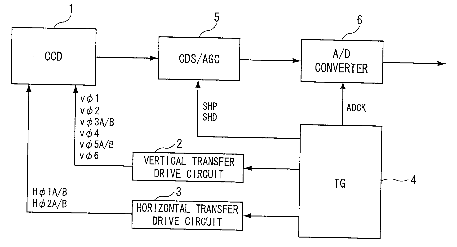
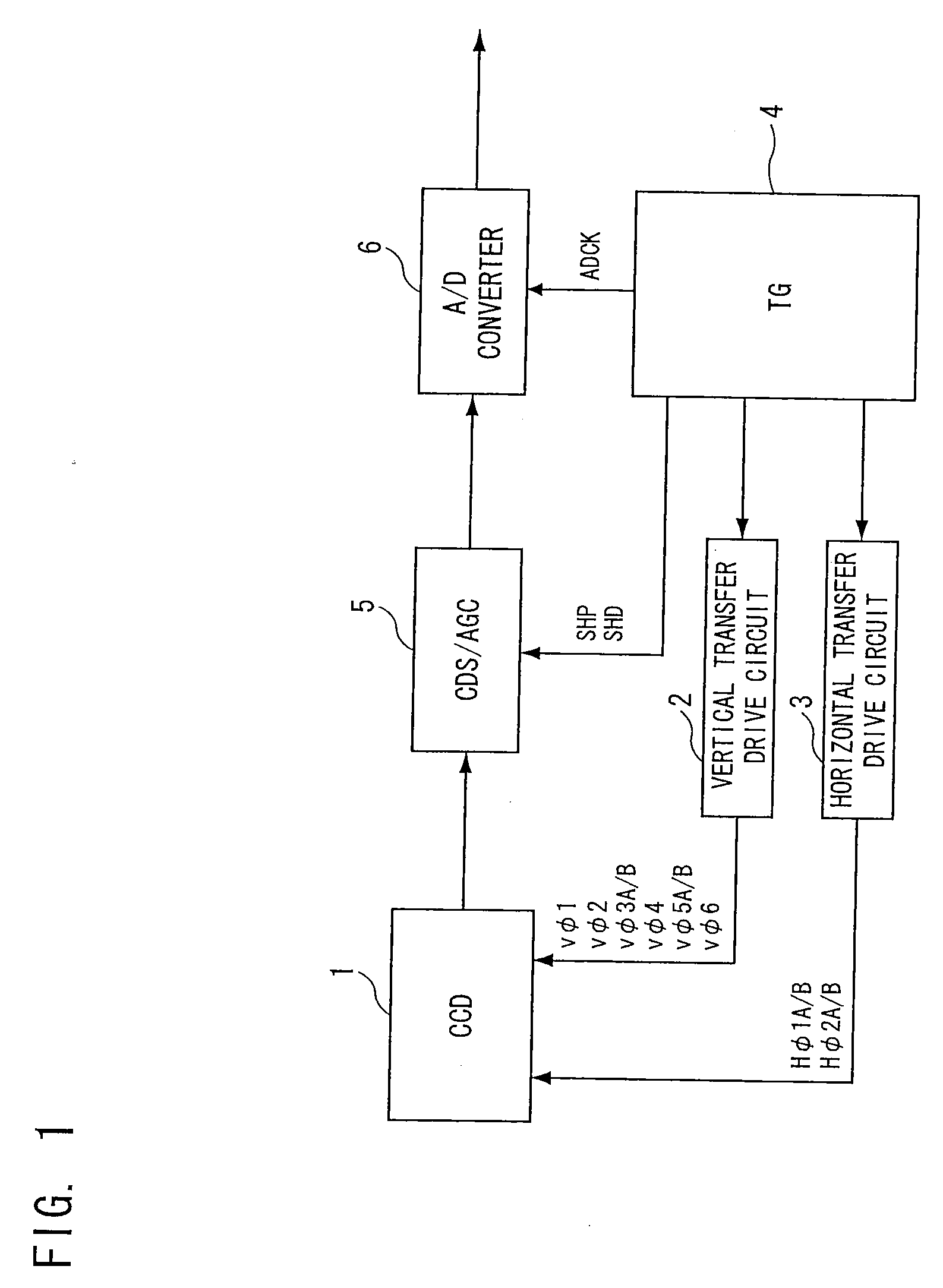
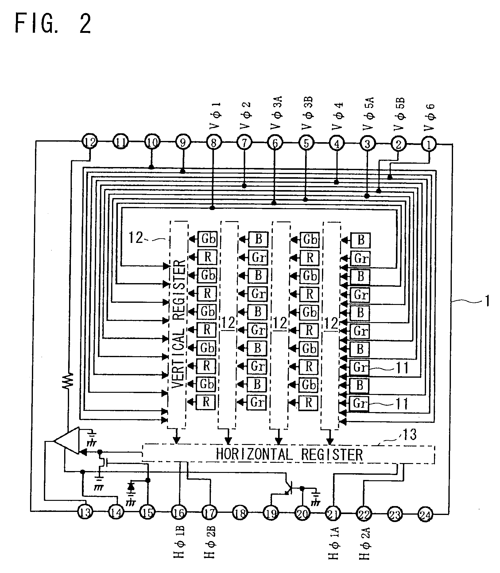
[0040] The present invention embodied in a drive unit for a solid-state image sensing device including a CCD will be specifically described below with reference to the drawings. A solid-state image sensing device drive unit of the present invention is for driving a solid-state image sensing device 1 shown in FIG. 2. The solid-state image sensing device 1 has an input terminal 8 for a first vertical transfer pulse Vφ1 having a first phase, an input terminal 7 for a second vertical transfer pulse Vφ2 having a second phase, input terminals 6, 5 for a pair of third vertical transfer pulses Vφ3A and Vφ3B having a third phase, an input terminal 4 for a fourth vertical transfer pulse Vφ4 having a fourth phase, input terminals 3, 2 for a pair of fifth vertical transfer pulses Vφ5A and Vφ5B having a fifth phase, and an input terminal 1 for a sixth vertical transfer pulse Vφ6 having a sixth phase. Feeding these vertical transfer pulses to the respective input terminals causes electric charges...


PUM


Abstract

A solid-state image sensing device drive unit of the present invention includes a randomly accessible SRAM for storing waveform information on a drive signal for a solid-state image sensing device, and a comparator for reading the waveform information from the SRAM and creating the drive signal based on the read waveform information.

Description

FIELD OF THE INVENTION [0001] The present invention relates to a drive unit for a solid-state image sensing device including a CCD or the like. BACKGROUND OF THE INVENTION [0002]FIG. 2 shows a configuration of an interline transfer solid-state image sensing device 1 used for a digital still camera. The solid-state image sensing device 1 forms an imaging area including a plurality of pixels 11 by having color filter arrays on a plurality of photo sensors arranged in the form of a matrix, and has a plurality of vertical registers 12 for transferring electric charges of a plurality of arrays of vertically arranged pixels 11, and a horizontal register 13 for outputting the electric charges transferred by these vertical registers 12 every one horizontal period. [0003] The above solid-state image sensing device 1 has an input terminal 8 for a first vertical transfer pulse Vφ1 having a first phase, an input terminal 7 for a second vertical transfer pulse Vφ2 having a second phase, input te...

Claims


Application Information

Patent Timeline
IPC IPC(8): G01N21/01H04N5/335H04N5/341H04N5/3728H04N5/376
CPCH04N5/335H04N25/00
Inventor KIDO, KENICHI
Owner SANYO ELECTRIC CO LTD
Why Eureka
Try Eureka