Optical Device

Inactive Publication Date: 2007-02-22
CANON KK
View PDF5 Cites 17 Cited by
  • Summary
  • Abstract
  • Description
  • Claims
  • Application Information

AI Technical Summary

Benefits of technology

[0029] The present invention provides an optical device including electroactive polymer actuators for driving lenses having hig

Problems solved by technology

However, each measure may cause an increase in the size of the motors, and does not match the tendency toward smaller image-forming apparatuses in recent years.
When a decelerating mechanism is employed, driving noise of the motor and noise of gears of the decelerating mechanism are disadvantageously generated since the motor drives at a speed higher than that of the load.
Moreover, mechanical components added to the decelerating mechanism and the lever may prevent size reduction and low costs, and may impair durability due to mechanical sliding portions thereof.
Application of the cylindrical actuator according to U.S. Pat. No. 6,891,317 to an actuator for driving a lens leads to the following problems:
The first problem is that the layout of the actuator installed inside a lens barrel is performed with low flexibility.
Therefore, even when the size of the cylindrical actu

Method used


Image

  • Optical Device
  • Optical Device
  • Optical Device

Examples


Example

First Exemplary Embodiment

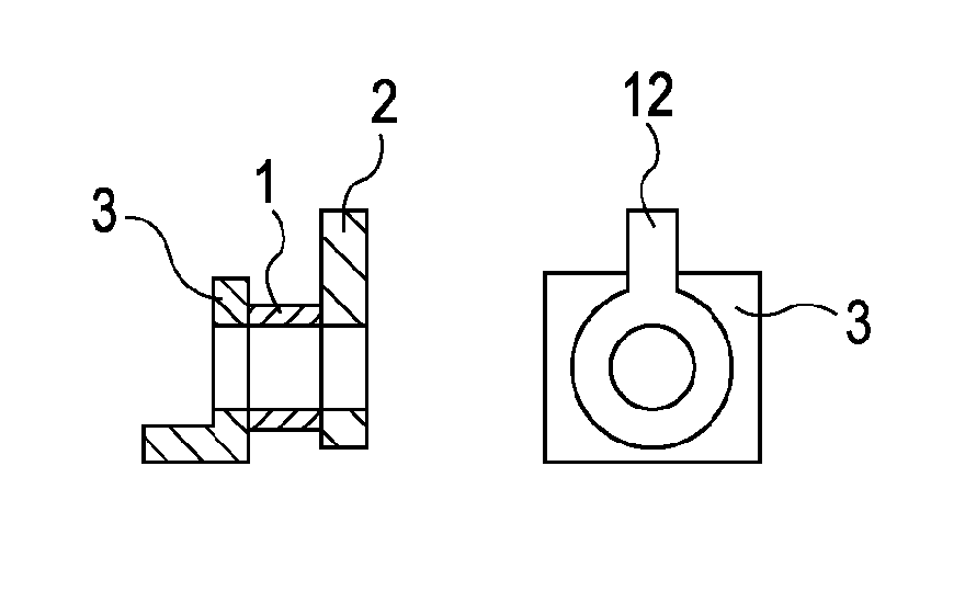
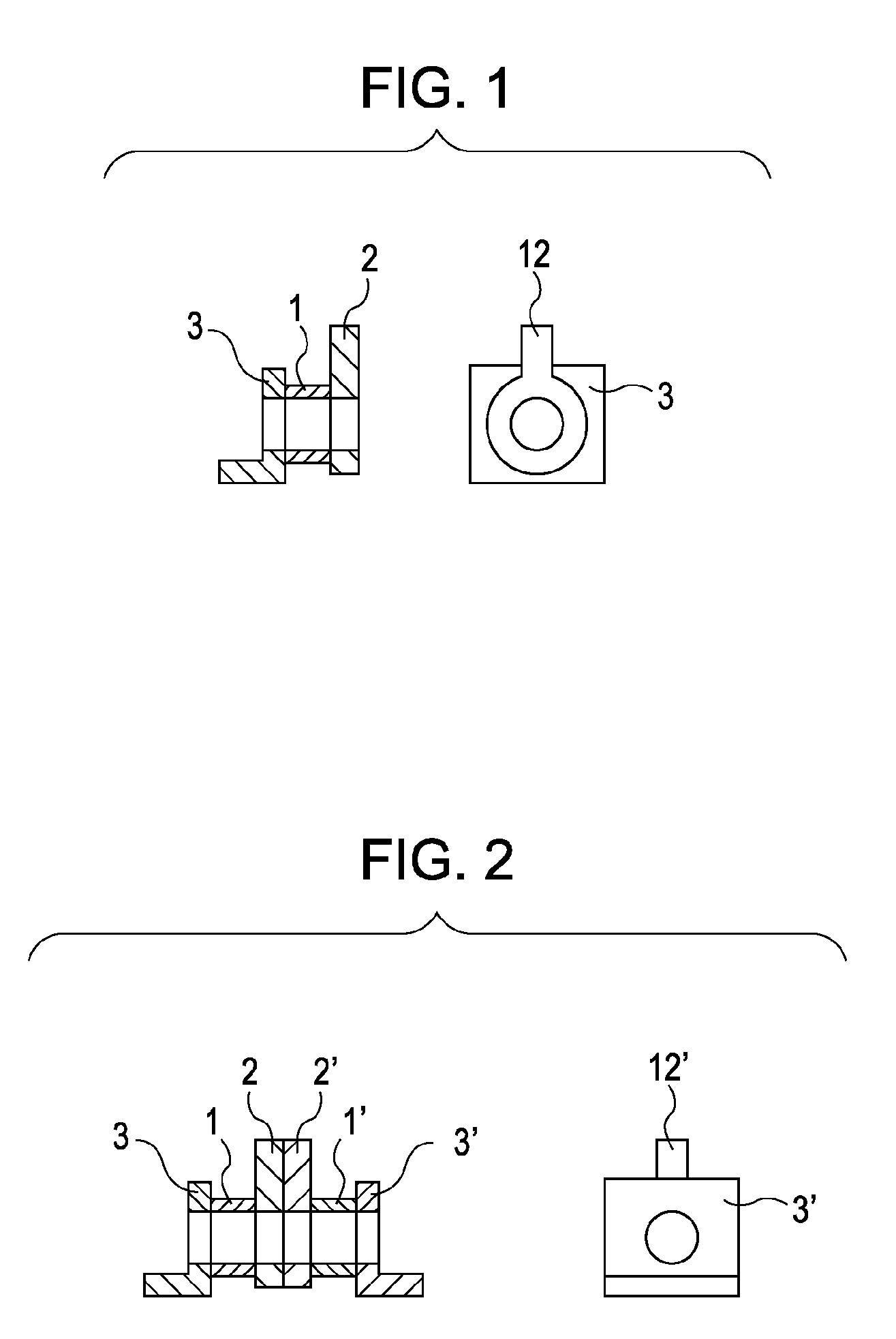
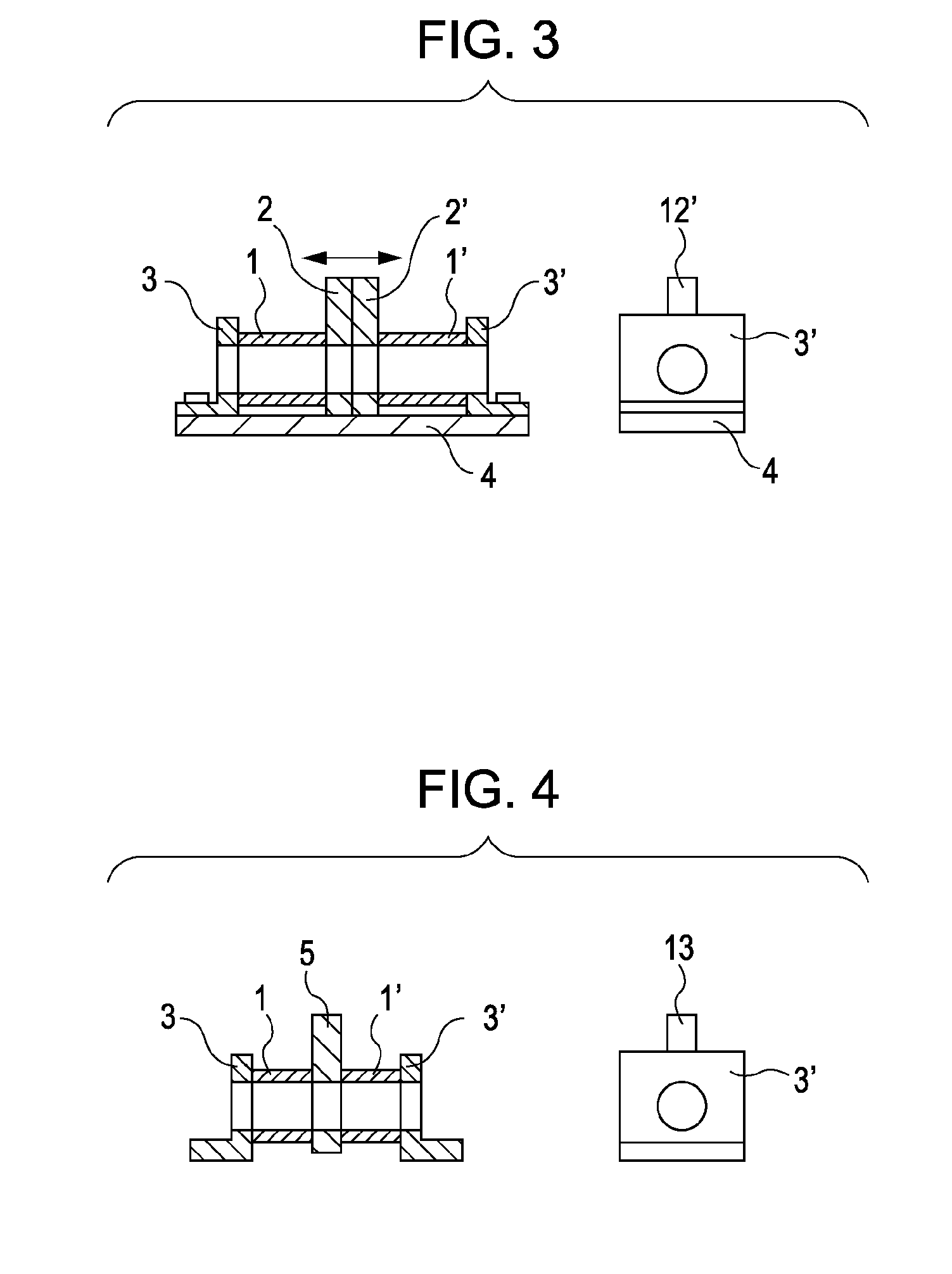
[0047] FIGS. 1 to 5 illustrate structures of actuators according to a first exemplary embodiment.

[0048] Cylindrical actuator elements 1 and 1′ are composed of an electroactive polymer. In this exemplary embodiment, the material may be an acrylic or silicone dielectric elastomer disclosed in U.S. Pat. No. 6,891,317, or may have properties shown in Table 1 (J. D. W. Madden; Artificial Muscle Technology: Physical Principles and Naval Prospects; IEEE Journal of Oceanic Engineering; July 2004, Vol. 29, No. 3). However, the material is not limited to these.

[0049] Holding members 2, 3, and 5 are mechanical components for holding the actuator elements 1 and 1′, and are bonded to either end of the actuator elements 1 and 1′. Moreover, the holding members 2 and 5 include keys 12 and 13, respectively, that are mechanically connected to loads. In this exemplary embodiment, the driving force of the actuators is transmitted via the keys 12 and 13. Flat plates 4 apply ...

Example

Second Exemplary Embodiment

[0067] An actuator unit according to another exemplary embodiment will now be described with reference to FIGS. 6 and 7.

[0068] In order to prestrain the actuator elements, a stepped shaft 18 shown in FIGS. 6 and 7 may be employed in this exemplary embodiment instead of the flat plate according to the above-described exemplary embodiment.

[0069] In this case, a holding member 14 has a tapped hole 14a that is engaged with a threaded portion 18a of the stepped shaft 18. The leading end 18b of the stepped shaft 18 is fitted into a hole 15a of a holding member 15 while the threaded portion 18a proceeds into the tapped hole 14a of the holding member 14, and the stepped portion of the stepped shaft 18 presses the holding member 15. The actuator elements 1 and 1′ are extended and prestrained while the threaded portion 18a further proceeds into the tapped hole 14a. The holding member 5 can slide on the stepped shaft 18. The hole of the holding member 5 and the sl...

Example

Third Exemplary Embodiment

[0071] Next, a third exemplary embodiment will be described with reference to FIGS. 10, 11, 17, 18, and 19. FIGS. 10 and 11 illustrate the structure according to the third exemplary embodiment. The structure of the actuator unit according to the third exemplary embodiment is the same as that of the actuator unit according to the first exemplary embodiment shown in FIG. 4 except that the actuator unit according to the third exemplary embodiment includes a shaft 19. The shaft 19 is clamped to the holding member 5 so as to be integrated with the holding member 5. The shaft 19 is engaged with holes of the holding members 3 and 3′ so as to be slidable. The holes of the holding members 3 and 3′ are covered with a low-friction coating as in the second exemplary embodiment. FIG. 10 illustrates the actuator unit before the actuator elements 1 and 1′ are prestrained. FIG. 11 illustrates the actuator unit when the holding members 3 and 3′ are fixed to the flat plate ...


PUM


Abstract

An optical device includes a lens holder that holds a lens and is movable in the optical-axis direction of the lens, and an actuator that moves the lens holder in the optical-axis direction. The actuator includes an actuator element composed of an electroactive polymer, an actuator-element holder that holds the actuator element, a mechanism that applies prestrain to the actuator element, and a connecting member that connects the lens holder and the actuator. Herein, a connecting portion of the connecting member is disposed adjacent to the side surface of the actuator.

Description

CROSS-REFERENCE TO RELATED APPLICATION [0001] This application claims the benefit of U.S. Provisional Application No. 60 / 708,488, filed Aug. 16, 2005 and U.S. Provisional Application No. 60 / 728,132, filed Oct. 19, 2005, which are hereby incorporated by reference in their entirety.BACKGROUND OF THE INVENTION [0002] 1. Field of the Invention [0003] The present invention relates to image-forming apparatuses such as video cameras and electronic still cameras, and in particular, relates to optical devices using electroactive polymer actuators. [0004] 2. Description of the Related Art [0005] There has been significant size reduction of video cameras and electronic still cameras in recent years. At the same time, ultrasmall camera units for cellular phones and the like have been developed in succession, and the demand for smaller image-capturing lens units is increasing. [0006] To date, electromagnetic motors have been generally used as actuators for driving movable lenses and light-adjust...

Claims


Application Information

Patent Timeline
IPC IPC(8): H02N11/00
CPCG02B7/023G02B7/08H02N11/006Y10S310/80
Inventor OGINO, SHIGERU
Owner CANON KK
Why Eureka
Try Eureka