
Tapered roller bearing, tapered roller bearing apparatus, and automotive pinion shaft supporting apparatus utilizing same tapered roller bearing apparatus

a tapered roller bearing and tapered roller bearing technology, which is applied in the direction of roller bearings, mechanical equipment, bearings, etc., can solve the problems of easy seized large diameter side end deteriorated lubricity between large diameter side end faces and end faces of large ribs, etc., to facilitate oil inflow and reduce running torque

Active Publication Date: 2007-02-22
JTEKT CORP
View PDF9 Cites 12 Cited by
  • Summary
  • Abstract
  • Description
  • Claims
  • Application Information

AI Technical Summary

Benefits of technology

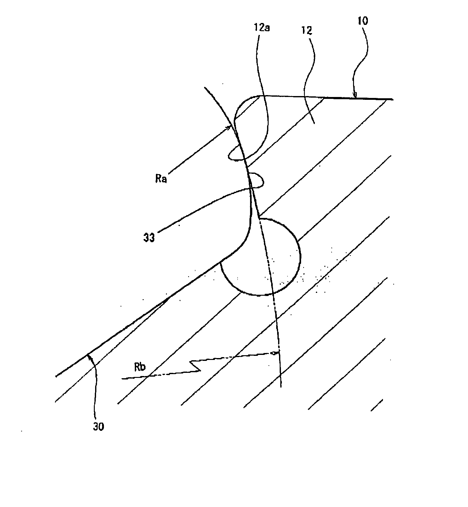
[0005] The invention was made in view of the situations, and an object thereof is to provide a tapered roller bearing which can increase the lubricity between the large diameter side end face of the tapered roller and the end face of the large rib portion of the inner ring to thereby suppress the occurrence of seizing on the large diameter side end face or the end face of the large rib portion, a tapered roller bearing apparatus utilizing the tapered roller bearing and an automotive pinion shaft supporting apparatus which utilizes the tapered roller bearing apparatus.

Problems solved by technology

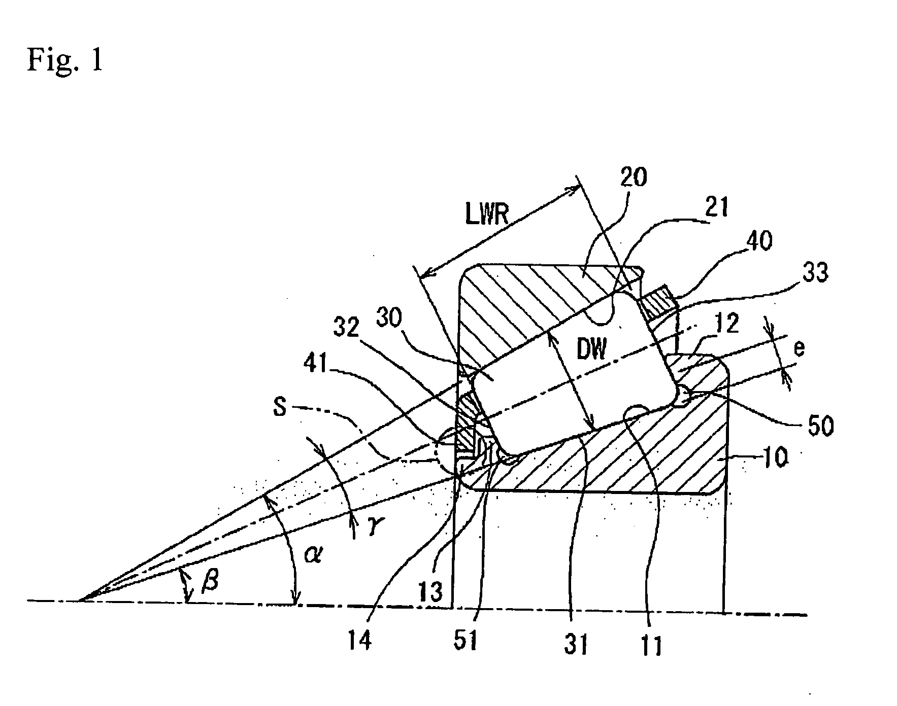
In the aforesaid case, however, when a tapered roller is machined with the plus side tolerance, since a contact position between the large diameter side end face of the tapered roller and the end face of the large rib portion of the inner ring becomes high (the value of e in FIG. 1 increases), the lubricity between the large diameter side end face and the end face of the large rib portion was deteriorated, and as a result, there was caused a problem that the large diameter side end face of the end face of the large rib portion tended to get seized easily.

Method used


Image

  • Tapered roller bearing, tapered roller bearing apparatus, and automotive pinion shaft supporting apparatus utilizing same tapered roller bearing apparatus
  • Tapered roller bearing, tapered roller bearing apparatus, and automotive pinion shaft supporting apparatus utilizing same tapered roller bearing apparatus
  • Tapered roller bearing, tapered roller bearing apparatus, and automotive pinion shaft supporting apparatus utilizing same tapered roller bearing apparatus

Examples


Embodiment Construction

[0036] Hereinafter, a tapered roller bearing, a tapered roller bearing apparatus and an automotive pinion shaft supporting apparatus according to an embodiment of the invention will be described in detail by reference to the accompanying drawings.

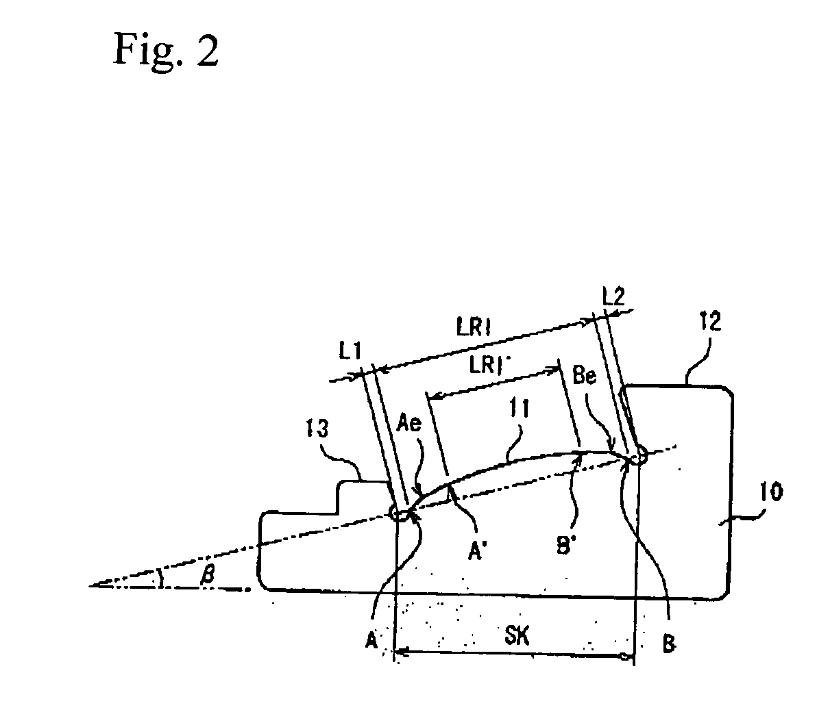
[0037]FIG. 1 is an axial sectional view of a tapered roller bearing according to an embodiment of the invention. This tapered roller bearing is used on a pinion gear side of an automotive differential as an automotive pinion shaft supporting apparatus and includes an inner ring 10 in which an inner ring raceway surface 11 made up of a coned surface is formed on an outer circumference thereof, an outer ring 20 in which an outer ring raceway surface 21 made up of a coned surface is formed on an inner circumference thereof, a plurality of tapered rollers 30 interposed between the inner and outer rings and each having a rolling contact surface 31 which is made up of a coned surface and is formed on an outer circumference thereof, and a case 40...


PUM


Abstract

A tapered roller bearing includes an outer ring, an inner ring, a plurality of tapered rollers interposed between the outer ring and the inner ring, and a cage for the tapered rollers. Ra is smaller than Rb where Ra represents a radius of curvature of a large end face of the tapered roller and Rb represents a radius of curvature of an end face of a large rib portion of the inner ring.

Description

BACKGROUND OF THE INVENTION [0001] The present invention relates to a tapered roller bearing which is used in differentials for motor vehicles and industrial machines, a tapered roller bearing apparatus which utilizes the tapered roller bearing and an automotive pinion shaft supporting apparatus which utilizes the tapered roller bearing apparatus. [0002] Since tapered roller bearings are characterized in that they have a high load capacity and a high rigidity, compared to ball bearings, the tapered roller bearings are used in automotive pinion shaft supporting apparatuses in differentials and transaxles of motor vehicles. [0003] In the tapered roller bearing, conventionally, in order to reduce a sliding friction between a large diameter side end face of a tapered roller and a large rib portion of an inner ring so as to reduce the running torque of the tapered roller bearing, the large diameter side end face of the tapered roller was formed into a convexly curved surface. In forming ...

Claims


Application Information

Patent Timeline
IPC IPC(8): F16C33/58F16C19/36F16C33/36F16C33/46F16C33/66F16C33/80F16H57/021F16H57/037F16H57/038F16H57/039
CPCF16C19/225F16C19/364F16C23/088F16C33/64F16C2240/70F16C2361/61F16C33/585F16C33/366F16C2240/50
Inventor MASUDA, NAOKITODA, KAZUTOSHIMATSUYAMA, HIROKIKAWAGUCHI, KOUJIOHSHIMA, HIROYUKI
Owner JTEKT CORP
Learn More