Cooling circuit for gas turbine fixed ring

a gas turbine and fixed ring technology, which is applied in the direction of machines/engines, stators, liquid fuel engines, etc., can solve the problems of reducing the performance of the turbine, the amount of cooling air, and the inability to achieve so as to reduce the air flow needed, the effect of effective and uniform cooling of the ring segments and high heat exchange coefficien

Active Publication Date: 2007-02-22
SN DETUDE & DE CONSTR DE MOTEURS DAVIATION S N E C M A
View PDF13 Cites 57 Cited by
  • Summary
  • Abstract
  • Description
  • Claims
  • Application Information

AI Technical Summary

Benefits of technology

[0006] The present invention thus seeks to mitigate such drawbacks by proposing a stationary ring for a gas turbine in which each ring segment is provided with internal cooling circuits that require only a small flow of air, and enabling the ring segment to be cooled effectively by thermal convection.
[0008] The top and bottom internal cooling circuits benefit from high heat exchange coefficients in order to provide effective and uniform cooling of each ring segment. These circuits make it possible in particular to cool the ring segment zones that are the most exposed to the hot gas. It is thus possible to reduce the air flow needed for cooling the ring segments, even under severe thermodynamic conditions of turbine operation.
[0009] As a result, the lifetime of the stationary ring of the turbine can be increased and the performance of the turbine is little affected by the air that is taken for cooling the ring segments.
[0010] The top cooling circuit serves in particular to cool the upstream end of the ring segment and to improve the effectiveness of the bottom cooling circuit. The bottom cooling circuit serves to cool the inside surface of the ring segment, and possibly of the adjacent ring segments.
[0011] The top and bottom internal cooling circuits are independent of each other, which presents the advantages of enabling the cooling that is performed by each cooling circuit to be independent and of enabling the air flow fed to each circuit to be adapted thereto. For example, a large flow could be used for the top circuit in order to cool the upstream end of the ring segment effectively (i.e. the hottest zone thereof), while a smaller flow could be used for the bottom circuit. The independence between the cooling circuits also makes it possible to optimize cooling in independent manner.

Problems solved by technology

Such a method does not enable effective and uniform cooling of the ring segments to be obtained, particularly at the upstream ends of the ring segments which constitute a zone that is particularly exposed to hot gas.
Furthermore, that technology requires too great an amount of cooling air to be taken, thereby decreasing the performance of the turbine.

Method used


Image

  • Cooling circuit for gas turbine fixed ring
  • Cooling circuit for gas turbine fixed ring
  • Cooling circuit for gas turbine fixed ring

Examples


Embodiment Construction

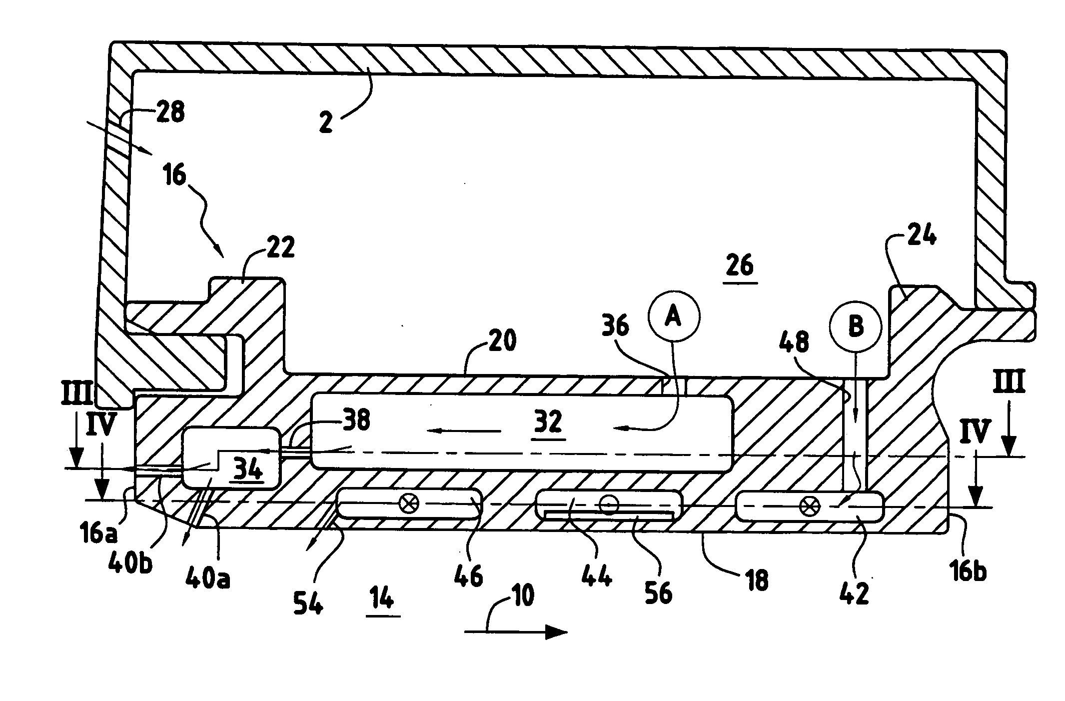
[0018] Reference is made initially to FIG. 1 which is a diagram showing a portion of a high pressure turbine 1 of a turbomachine.

[0019] The high pressure turbine 1 includes in particular a stationary annular housing 2 constituting a casing of the turbomachine. A stationary turbine ring 4 is secured to the housing 1 and surrounds a plurality of moving blades 6 of the turbine. These moving blades 6 are disposed downstream from stationary vanes 8 relative to the flow direction 10 of the hot gas coming from a combustion chamber 12 of the turbomachine and passing through the turbine. Thus, the ring 4 of the turbine surrounds a flow passage 14 for hot gas.

[0020] In general, the turbine ring 4 comprises a plurality of ring segments disposed circumferentially around the axis of the turbine (not shown) so as to form a continuous circular surface. Nevertheless, it is also possible for the turbine ring to be constituted by a single continuous part. The present invention applies equally well ...


PUM


Abstract

A stationary ring surrounding a hot gas passage in a gas turbine, the ring being surrounded by a stationary annular housing co-operating therewith to define an annular cooling chamber into which there opens out at least one cooling air feed orifice. The ring is made up of a plurality of ring segments, each ring segment including a top internal cooling circuit and a bottom internal cooling circuit. The bottom cooling circuit is independent of the top cooling circuit and is radially offset relative to the top cooling circuit.

Description

BACKGROUND OF THE INVENTION [0001] The present invention relates to stationary rings surrounding gas passages in a gas turbine, and more particularly it relates to cooling stationary rings in a gas turbine. [0002] A gas turbine, in particular a high pressure turbine of a turbomachine, typically comprises a plurality of stationary vanes alternating with a plurality of moving blades in the passage for hot gas coming from the combustion chamber of the turbomachine. The moving blades on the turbine are surrounded over their entire circumference by a stationary ring that is generally made up of a plurality of ring segments. These ring segments define part of the flow passage for hot gas passing through the blades of the turbine. [0003] The ring segments of the turbine are thus subjected to the high temperatures of the hot gas coming from the combustion chamber of the turbomachine. To enable the turbine ring to withstand the temperature and mechanical stresses to which it is subjected, it...

Claims


Application Information

Patent Timeline
Patent Type & Authority Applications(United States)
IPC IPC(8): F04D31/00F01D9/04F01D11/08F01D25/12
CPCF01D9/04F01D11/08F01D25/12F05D2260/202
Inventor CAMUS, STEPHANE
Owner SN DETUDE & DE CONSTR DE MOTEURS DAVIATION S N E C M A
Why Eureka
Try Eureka