
Machine for filling and sealing two-part capsules

a machine and capsule technology, applied in the direction of liquid materials, transportation and packaging, packaging goods types, etc., can solve the problems of major effort and expense in assembly of guide flaps, and the capsules that are free of defects can remain stuck on the good sid

Inactive Publication Date: 2007-03-01
ROBERT BOSCH GMBH
View PDF11 Cites 9 Cited by
  • Summary
  • Abstract
  • Description
  • Claims
  • Application Information

AI Technical Summary

Benefits of technology

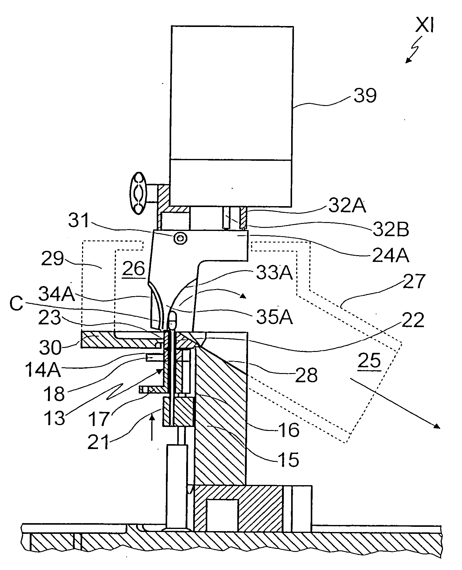
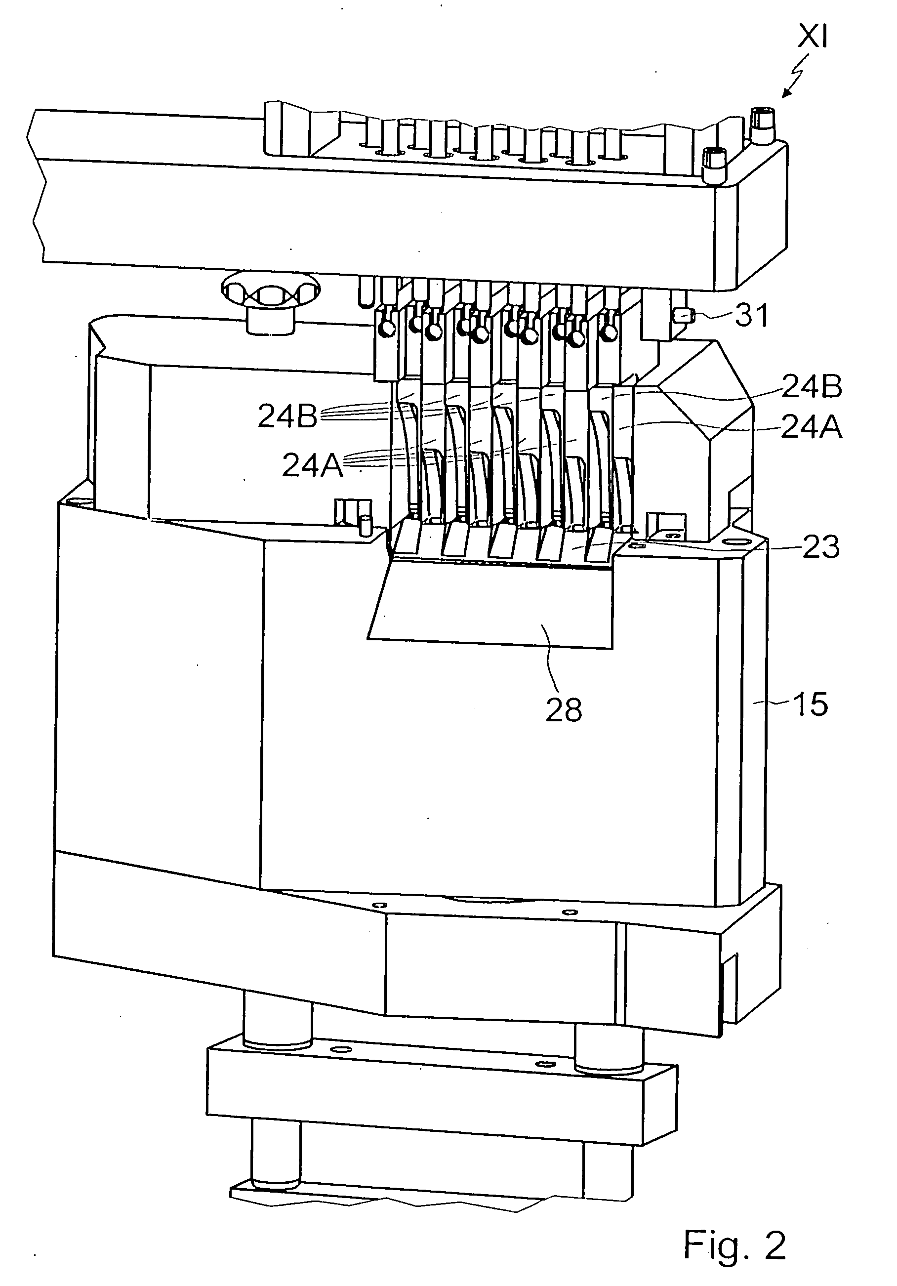
[0007] The machine according to the invention for filling and sealing two-part capsules, in particular hard gelatin capsules, having the characteristics of the preamble to claim 1, in which machine the partitions are each an integrated component of a guide flap, have the advantage that the capsule expulsion station can have a considerably more simply produced housing than the capsule expulsion station of a machine of the prior art, since separator ribs which are complicated to manufacture and service partitions are no longer needed between the individual receptacles of the capsule delivery device.
[0008] Because of the absence of separator ribs, the housing of the capsule expulsion station is also easier to clean.
[0009] Because a gap between a body of the guide flaps that forms the guideways and an adjacent partition is also omitted, the risk that with suction support of a guideway associated with a bad side, for instance, defect-free capsules may unintentionally remain adhering to a guideway associated with a so-called good side, since the air flow from the guideway associated with the good side to the guideway associated with the bad side is reduced markedly.
[0010] In a preferred embodiment of the machine of the invention, which is easy to assemble, the various guide flaps that have a shunt function are supported on a common pivot shaft. This makes it possible to slip the guide flaps as packet onto the pivot shaft during assembly.
[0013] The position of the respective guide flap upon expulsion of the respective capsule from its receptacle in the capsule delivery device is preferably dependent on the quality or fill level of the respective capsules, ascertained at at least one inspection station for the capsules. If a capsule is found good in the inspection station, the applicable guide flap is pivoted into a position such that the capsule, along the guideway associated with the good side, is expelled into a suitable container. If a capsule in the inspection station is found to be bad, that is, defective, then the corresponding guide flap is pivoted such that the capsule is expelled along the guideway associated with the bad side. For this purpose, a control device of the actuating device for the guide flaps preferably cooperates with the inspection station for the capsules.
[0014] Further advantages and advantageous features of the subject of the invention can be learned from the description, the drawings, and the claims.

Problems solved by technology

Another disadvantage is the embodiment of a comparatively large gap between each of the individual guide flaps and the separator ribs, so that there is the risk that upon an expulsion, reinforced by suction, on the bad side of the affected guide flap, defect-free capsules can remain “stuck” on the good side.
Moreover, because of how the receptacles for the capsules in the delivery device are disposed and because the guide flaps are embodied uniformly, each guide flap has its own pivot shaft, which in turn entails major effort and expense for assembling of the guide flaps.

Method used


Image

  • Machine for filling and sealing two-part capsules
  • Machine for filling and sealing two-part capsules
  • Machine for filling and sealing two-part capsules

Examples


Embodiment Construction

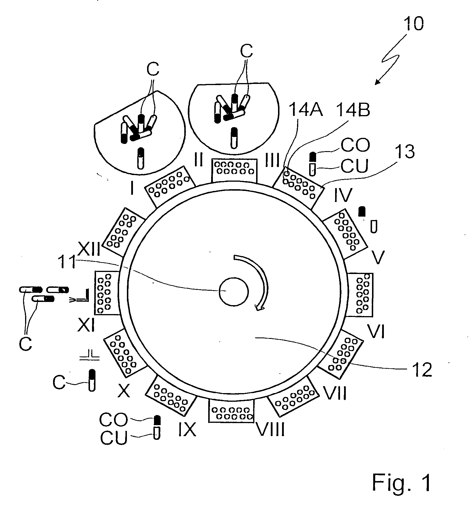
[0028] In FIG. 1, a machine 10 for filling and sealing capsules C is shown, each capsule comprising one lower capsule part CU and upper capsule part or cap CO. The machine 10 includes, as a capsule delivery device, a feed wheel 12 rotating in increments about a vertical shaft 11, by means of which wheel twelve work stations I through XII can be approached. To this end, the capsule delivery device 12 includes twelve carriers 13, in each of which two rows offset from one another longitudinally are embodied, each containing five receptacles 14A and 14B, each for one of the capsules C.

[0029] The individual work stations I through XII of the machine 10 have different tasks in the filling of the capsules C.

[0030] For instance, at work stations I and II, the capsules C that have been put together are sorted and introduced into the receptacles 14A of the first row and into the receptacles of the second row 14B of the respective carrier 13.

[0031] After the feed wheel 12, or the carrier 13...


PUM

PropertyMeasurementUnit
Currentaaaaaaaaaa
Currentaaaaaaaaaa
Currentaaaaaaaaaa

Abstract

A machine for filling and sealing two-part capsules (C), in particular hard gelatin capsules, is proposed. The machine includes a capsule delivery device, which has receptacles (14A), each for one capsule (C). The further includes at least one capsule expulsion station (XI), which has a capsule expulsion device (19) for axially expelling the capsules (C) from the respective receptacle (14A); guide flaps (24A, 24B) which are individually controllable by means of an actuating device (39) and are pivotable relative to a pivot shaft (31) and are each assigned to one capsule receptacle (14A) and which each have two guideways (33A, 34A), triggerable by means of the actuating device (39), for the respective associated capsules (A); and partitions, which separate the guideways (33A, 34A) of adjacent guide flaps (24A, 24B) from one another. The partitions are each an integrated component of one guide flap (24A, 24B) (FIG. 3).

Description

PRIOR ART [0001] The invention is based on a machine for filling and sealing two-part capsules of the type defined in further detail in the preamble to claim 1. [0002] Such a machine is known in the industry and is used in the pharmaceutical field for filling capsules, comprising a lower capsule part and an upper capsule part, with a medication that is for instance in powdered form. The machine includes a plurality of work stations, through which capsules located on a delivery device pass; the delivery device for instance comprises a first feed wheel, provided with receptacles for the lower capsule parts, and a second feed wheel, provided with receptacles for the upper capsule parts. [0003] The work stations include at least one capsule separating station, at which the upper capsule part is separated from the lower capsule part; a filling station for filling the lower capsule part with the powder, a capsule closing station, at which the upper capsule part is placed back on the lower...

Claims


Application Information

Patent Timeline
IPC IPC(8): B65B3/00A61J3/07
CPCA61J3/074
Inventor RUNFT, WERNERBOEHRINGER, WALTERBOEE, JARLE
Owner ROBERT BOSCH GMBH
Learn More