Three chamber hydraulic cylinder for an active vehicle suspension with integrated load leveling

a technology of hydraulic cylinders and active vehicles, applied in the direction of machines/engines, mechanical equipment, transportation and packaging, etc., can solve the problems of increasing mechanical fatigue of components, reducing reliability, and affecting the productivity of work vehicles

Inactive Publication Date: 2007-03-01
HUSCO INT INC
View PDF24 Cites 20 Cited by
  • Summary
  • Abstract
  • Description
  • Claims
  • Application Information

AI Technical Summary

Benefits of technology

[0018] Preferably the hydraulic actuator incorporates a displacement sensor which produces an electrical signal indicating an amount that the piston rod extends from the cylinder. For example, the displacement sensor includes an electrically resistive element attached to one of the cylinder, the piston and the piston rod. A wiper is attached to another one of the cylinder, the piston and the tubular piston rod, and moveably engages the resistive material. The wiper moves along the electrically resistive element as the piston rod extends and retracts with respect to the cylinder, thereby changing resistance across a pairs of electrical contacts connected of the displacement sensor.

Problems solved by technology

Vibration has an adverse affect on the productivity of work vehicles in which an operator cab is supported on a chassis.
The vibrations experienced by such vehicles reduce their reliability, increase mechanical fatigue of components, and most importantly produce human fatigue due to motion of the operator's body.
However, performance a lower frequencies, such as encountered by a farm tractor while plowing a field, was relatively poor.
Therefore, such previous vehicle suspension systems often performed poorly in the range of vibration frequencies to which the human body is most sensitive, i.e. one to ten Hertz.
However, the piston may drift toward one end of the cylinder due to changes in the load on the vehicle.
Other effects, such as leakage of hydraulic fluid and friction between the piston and the cylinder, also affect the position of the piston under static conditions.

Method used


Image

  • Three chamber hydraulic cylinder for an active vehicle suspension with integrated load leveling
  • Three chamber hydraulic cylinder for an active vehicle suspension with integrated load leveling
  • Three chamber hydraulic cylinder for an active vehicle suspension with integrated load leveling

Examples


Embodiment Construction

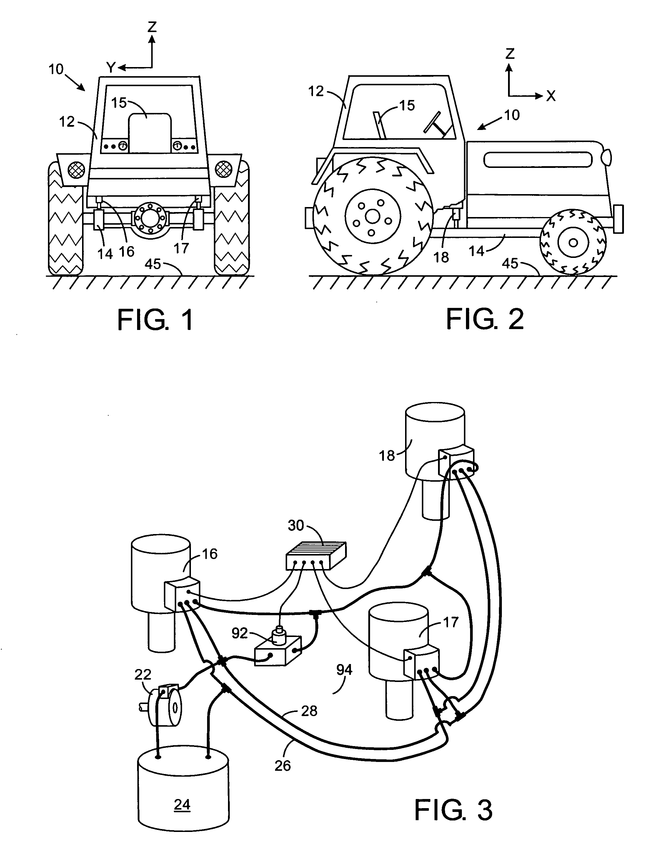
[0026] With reference to FIGS. 1 and 2, a vehicle 10, such as an agricultural tractor, has a cab 12 within which an operator sits on seat 15. The cab 12 is supported on the chassis 14 of the vehicle by three vibration isolators 16, 17 and 18. The first and second vibration isolators 16 and 17 are attached to the vehicle cab at the rear of the chassis 14. The third vibration isolator 18 is located at the center of the front of the cab 12. The three vibration isolators 16, 17 and 18 can be located at other positions underneath the cab and other numbers of isolators can be employed. Although the present invention is being described in the context of an isolation system which supports the cab12 of the vehicle 10, this system also could be employed to isolate only the operator seat 15 from the floor of the cab 12. Similar vibration isolators also could be incorporated into the suspension for each wheel of an automobile and used in vibration mitigating systems for other types of equipment...


PUM


Abstract

A hydraulic actuator for an active of semi-active vehicle suspension system has a cylinder with a piston therein. A piston rod is attached to the piston and extends out of the cylinder. First and second chambers are formed on opposites sides of the piston enabling the piston to be driven in a manner that counteracts vibrations in the vehicle, A third chamber is provided in the cylinder for connection to a load leveling apparatus. A novel structure reduces the overall length of the hydraulic actuator. A displacement sensor is incorporated into the hydraulic actuator to provide an electrical signal that indicated how far the piston rod extends from the cylinder.

Description

CROSS-REFERENCE TO RELATED APPLICATIONS [0001] Not Applicable STATEMENT REGARDING FEDERALLY SPONSORED RESEARCH OR DEVELOPMENT [0002] Not Applicable BACKGROUND OF THE INVENTION [0003] 1. Field of the Invention [0004] The present invention relates to active and semi-active hydraulic suspension systems for isolating a component, such as an operator cab or a seat, from vibrations in other sections of a vehicle while traveling over rough terrain; and more particularly to such hydraulic suspension systems which incorporate automatic load leveling. [0005] 2. Description of the Related Art [0006] Vibration has an adverse affect on the productivity of work vehicles in which an operator cab is supported on a chassis. Such vehicles include agricultural tractors, construction equipment, and over the road trucks. The vibrations experienced by such vehicles reduce their reliability, increase mechanical fatigue of components, and most importantly produce human fatigue due to motion of the operator...

Claims


Application Information

Patent Timeline
Patent Type & Authority Applications(United States)
IPC IPC(8): F01B1/00
CPCB60G13/14B60G17/015B60G99/008B60G2300/082B62D33/0608
Inventor SCHEDGICK, DAVID JAMESKAROLEK, MICHAEL J.
Owner HUSCO INT INC
Why Eureka
Try Eureka