Method for use with the pressure triggering of medical ventilators

a technology of pressure triggering and medical ventilator, which is applied in the direction of valve details, valve arrangements, life-saving devices, etc., can solve the problems of inability to overcome the resistance to the flow of breathing gases, inability to carry out sufficient respiratory activity by himself/herself, and inability to carry out adequate respiratory activity. , to achieve the effect of increasing the sensitivity of pressure and more economical design

Active Publication Date: 2007-03-01
GENERAL ELECTRIC CO
View PDF5 Cites 37 Cited by
  • Summary
  • Abstract
  • Description
  • Claims
  • Application Information

AI Technical Summary

Benefits of technology

[0011] The advantages of this invention include increased sensitivity of the pressure based detection of spontaneous patient breathing attempts. The invention also eliminates the need for additional flow sensors in the patient breathing circuit for triggering purposes, thus providing a more economical design.

Problems solved by technology

In some situations, such as those found in critical care units, emergency rooms, or operating rooms, a patient may be spontaneously breathing yet be too weak or sedated to carry out sufficient respiratory activity by himself / herself.
Or, the respiratory system of the patient may be injured or too inefficient for adequate respiration.
In these instances, the patient may start an inspiration of breathing gases but is not able to overcome the resistance to the flow of breathing gases in the breathing circuit to continue a full respiratory cycle.
This is due to the fact a pressure level to serve as a reference for a pressure triggering action has been difficult to establish with the necessary degree of accuracy.

Method used


Image

  • Method for use with the pressure triggering of medical ventilators
  • Method for use with the pressure triggering of medical ventilators
  • Method for use with the pressure triggering of medical ventilators

Examples


Embodiment Construction

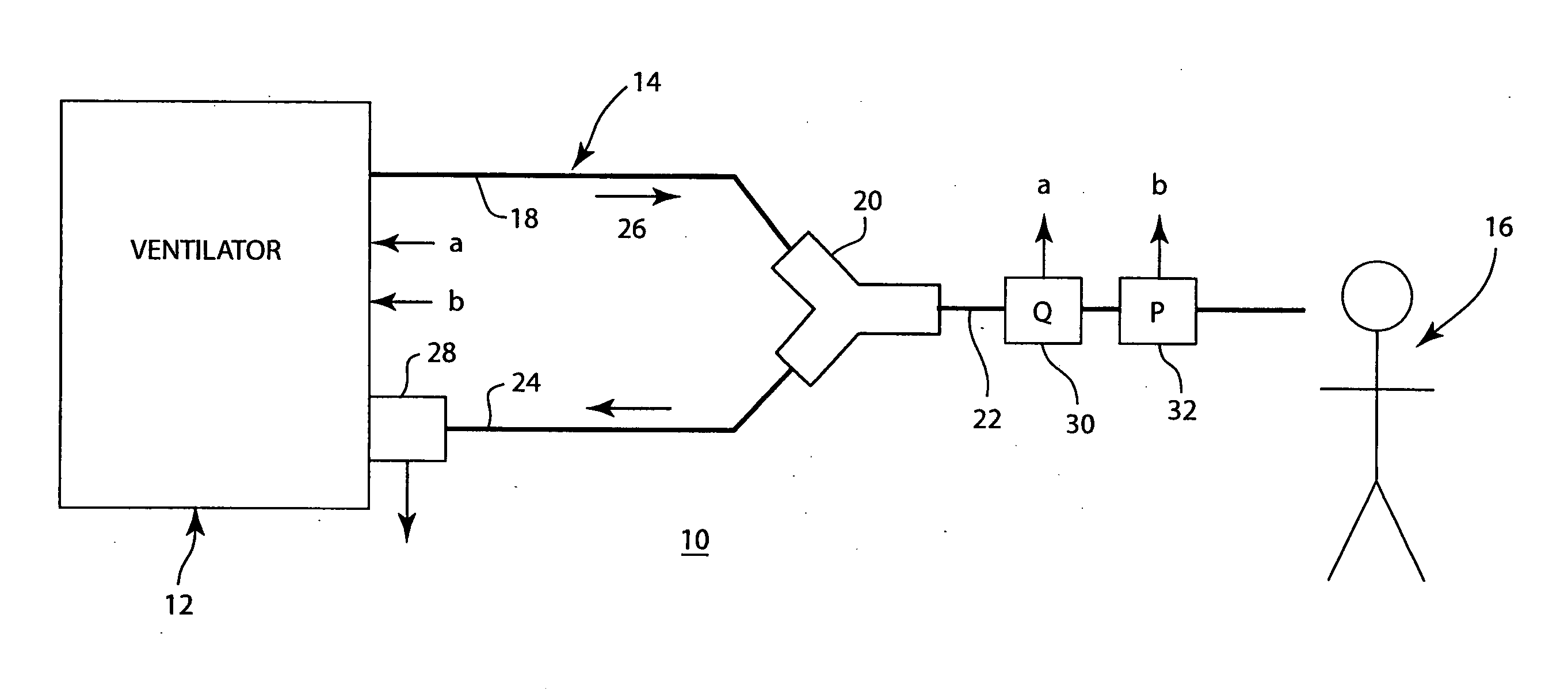
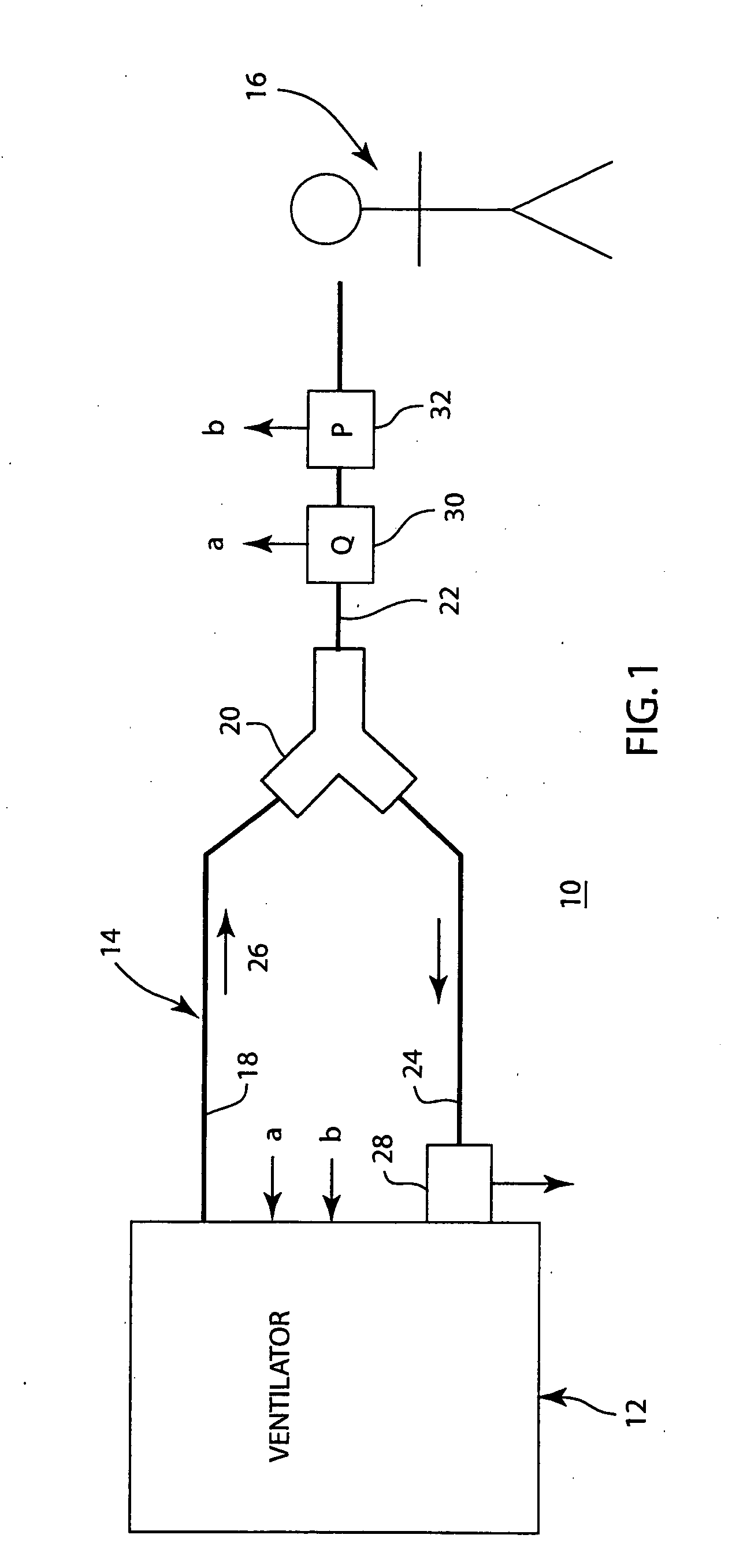
[0014] Referring now to the figures, FIG. 1 is a schematic diagram depicting a mechanical ventilator system 10 for use with the method of the present invention. The mechanical ventilator system comprises mechanical ventilator 12 and patient breathing circuit 14. Breathing circuit 14 is connected in gas communication with patient 16.

[0015] The patient breathing circuit 14 comprises an inspiratory limb 18, a Y-connector 20, a patient limb or connection 22 and an expiratory limb 24. Breathing gases from ventilator 12 flow in the direction of arrow 26 through the inspiratory limb 18 and Y-connector 20 to the patient via the patient limb 22 during inspiration. The breathing gases may be supplied to patient 16 by a respiratory mask, tent, endotracheal tube, nasal cannula, or other suitable device. The patient's expiratory breathing gases travel through patient limb 22, Y-connector 20, and expiratory limb 24 for return to an exhaust port 28 on the ventilator 12. One-way check valves (not ...


PUM


Abstract

A method for providing a pressure reference level for pressure triggering a ventilator responsive to a spontaneous breathing attempt by a patient. In the method, the patient connection of the breathing circuit is capped or plugged. A gas flow is then provided through the breathing circuit and is altered to an amount that causes the flow resistance properties of the breathing circuit to generate a desired gas pressure in the breathing circuit suitable for use as a reference pressure by the ventilator for pressure responsive triggering. During the operation of the ventilator, gas flow in a corresponding amount serves as a bias flow in the breathing circuit to assist breathing by the patient. The bias flow also generates the reference pressure level in the breathing circuit. A reduction in pressure from the pressure level resulting from inhalation by the patient triggers the operation of the ventilator.

Description

BACKGROUND OF THE INVENTION [0001] The present invention relates to establishing a reference pressure level for use in triggering the operation of a medical ventilator supplying breathing gases to a patient. Through use of the invention, the operation of the ventilator in supporting spontaneous breathing efforts by the patient may be enhanced. [0002] Patients in need of respiratory assistance are often placed on a mechanical ventilator. A mechanical ventilator is a device that provides breathing gas to a patient who is unable to breath, or alternatively, detects a patient's attempt to breathe and provides breathing gases to assist in that effort. The breathing gases typically comprise air, or air mixed with other gases, such as additional oxygen. The breathing gases are delivered to the patient from the ventilator via flexible tubes comprising the patient breathing circuit. [0003] The patient breathing circuit comprises an inspiratory limb which supplies the breathing gases to the p...

Claims


Application Information

Patent Timeline
Patent Type & Authority Applications(United States)
IPC IPC(8): A61M16/00
CPCA61M16/00A61M2016/0027A61M2016/0036A61M16/022
Inventor LEVI, ANDREW P.
Owner GENERAL ELECTRIC CO
Why Eureka
Try Eureka