
Heat exchanger

a technology of heat exchanger and side plate, which is applied in the direction of indirect heat exchanger, manufacturing tools, lighting and heating apparatus, etc., can solve the problems of difficulty in arranging the side plates at respective predetermined positions

Inactive Publication Date: 2007-03-01
KEIHIN THERMAL TECH CORP
View PDF8 Cites 23 Cited by
  • Summary
  • Abstract
  • Description
  • Claims
  • Application Information

AI Technical Summary

Benefits of technology

[0007] An object of the present invention is to solve the above problem and to provide a heat exchanger whose side plates can be accurately arranged at respectively predetermined positions, as well as a method of manufacturing the same.

Problems solved by technology

However, manufacturing the heat exchanger disclosed in the above publication involves difficulty in arranging the side plates at respectively predetermined positions.

Method used


Image

  • Heat exchanger
  • Heat exchanger
  • Heat exchanger

Examples


Embodiment Construction

[0055] An embodiment of the present invention will next be described in detail with reference to the drawings.

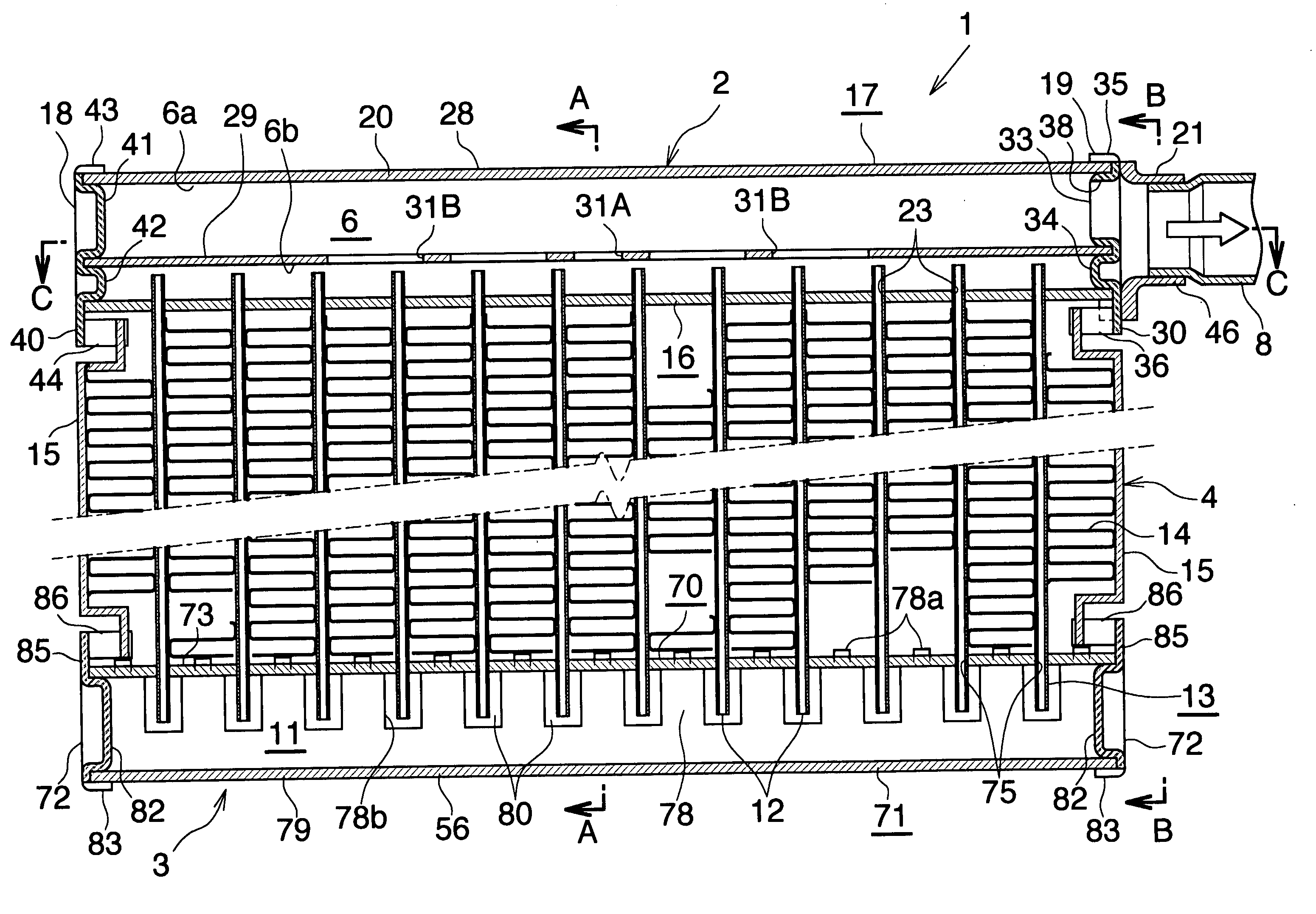
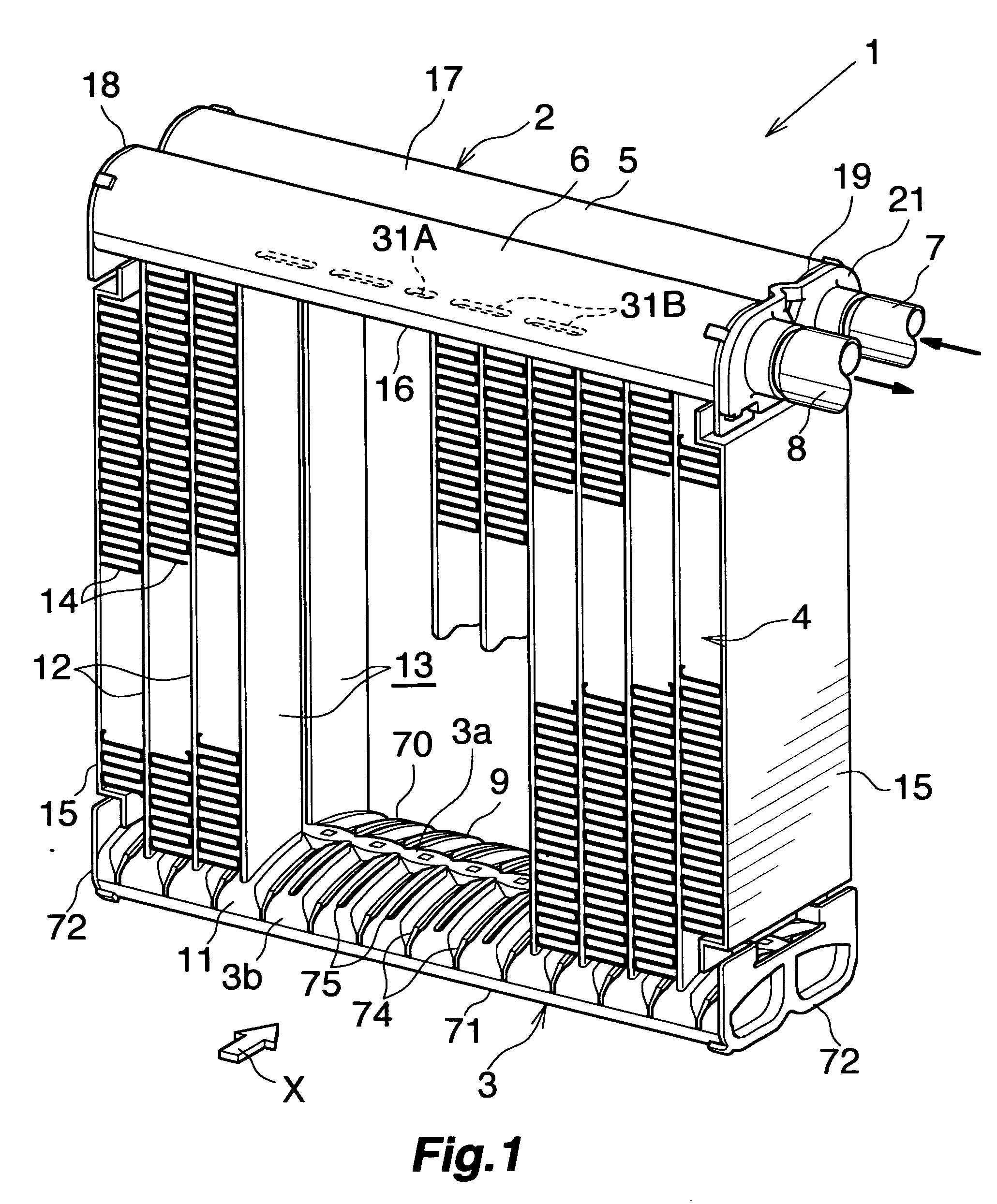
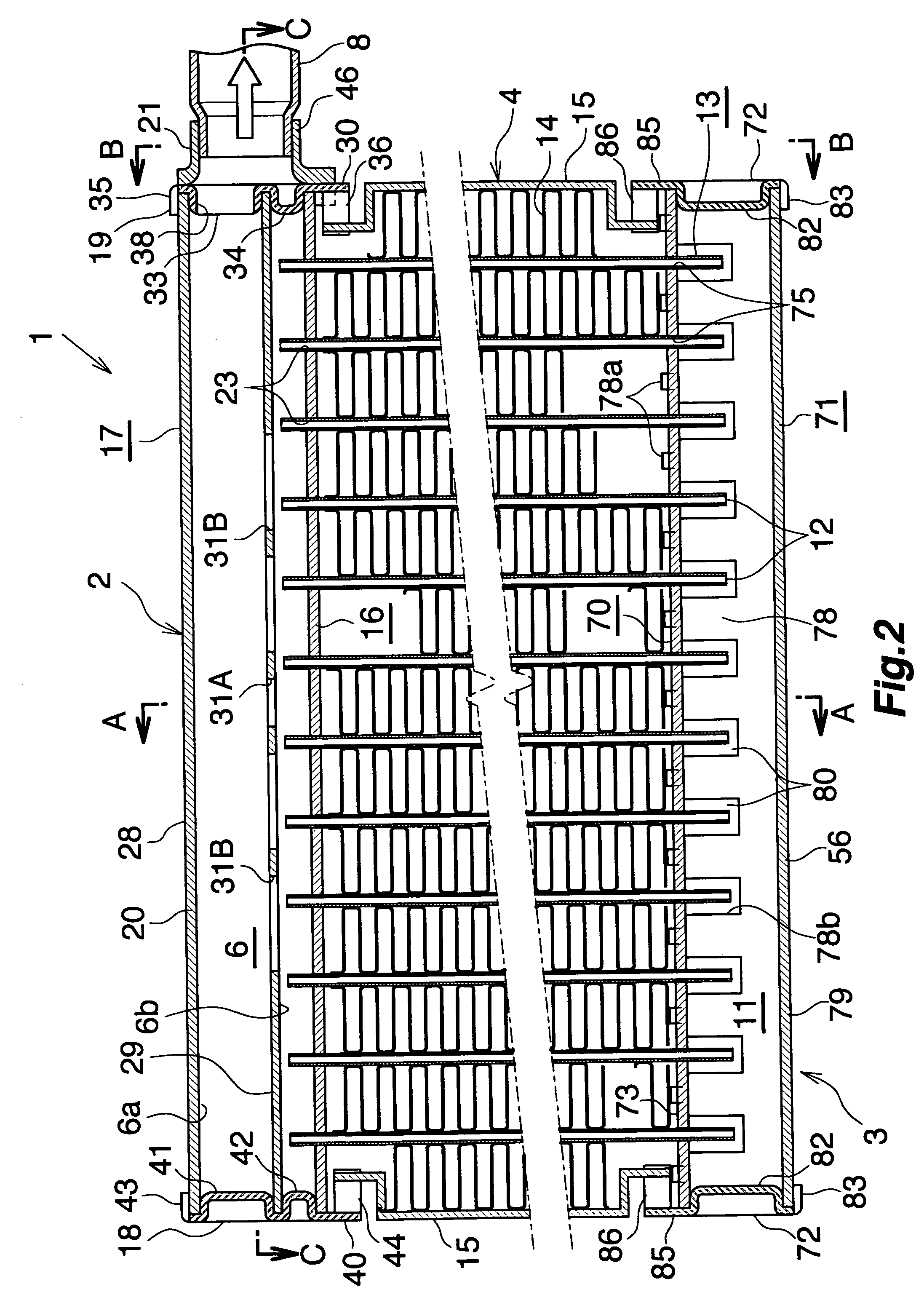
[0056] Herein, the term “aluminum” encompasses aluminum alloys in addition to pure aluminum. Also, the downstream side (a direction represented by arrow X in FIGS. 1 and 10; the right side of FIG. 4) of an air flow through air passing clearances between adjacent heat exchange tubes will be referred to as the “front,” and the opposite side as the “rear.” Further, the upper and lower sides of FIGS. 1 and 2 will be referred to as “up” and “down,” respectively.

[0057]FIGS. 1 and 2 show the overall configuration of an evaporator for a car air conditioner to which the present invention is applied. FIGS. 3 to 9 show the configuration of essential portions of the evaporator. FIG. 10 shows how a refrigerant flows in the evaporator.

[0058] In FIGS. 1 and 2, the evaporator 1, which is used in a car air conditioner using a chlorofluorocarbon-based refrigerant, includes a refrigerant in...


PUM

PropertyMeasurementUnit
widthaaaaaaaaaa
thicknessaaaaaaaaaa
heightaaaaaaaaaa

Abstract

In manufacture of a heat exchanger, heat exchange tubes, fins, and header section bodies are arrange in an assembled condition. Projection pieces provided on caps of header sections are fitted into corresponding slits formed in side plates, thereby engaging end portions of the side plates with the caps. In this condition, the caps are arranged in such a manner as to bridge end portions of the header section bodies, and the side plates are arranged on the outer sides of the leftmost and rightmost fins. The heat exchange tubes and the fins, the heat exchange tubes and the header section bodies, the header section bodies and the caps, the side plates and the caps, and the side plates and the fins are respectively brazed together simultaneously. This method enables the side plates to be accurately arranged at respectively predetermined positions.

Description

BACKGROUND OF THE INVENTION [0001] The present invention relates to a heat exchanger preferably used as an evaporator of a car air conditioner, which is a refrigeration cycle to be mounted on, for example, an automobile, and a method of manufacturing the same. [0002] Herein and in the appended claims, the left-hand and right-hand sides of FIG. 2 will be referred to as “left” and “right,” respectively. [0003] Conventionally, a so-called laminated evaporator has been widely employed as an evaporator for use in a car air conditioner. In the laminated evaporator, a plurality of flat, hollow members, each of which includes a pair of depressed plates facing each other and brazed to each other at their peripheral edge portions, are arranged in parallel, and corrugate fins are each disposed between and brazed to the adjacent flat, hollow members. [0004] However, in recent years, evaporators have been demanded to further reduce size and weight and to exhibit higher performance. The present a...

Claims


Application Information

Patent Timeline
Patent Type & Authority Applications(United States)
IPC IPC(8): F28D7/06F28D1/04
CPCF28D1/05391F28F9/001F28F9/0214F28F9/0246F28F2220/00
Inventor OHASHI, HIDEO
Owner KEIHIN THERMAL TECH CORP
Learn More