

Radiation detector and verification technique of positioning accuracy for radiation detector
a radiation detector and positioning accuracy technology, applied in the field of radiation detectors, can solve the problems of long time-consuming and laborious operation of detector operators, inability to accurately indicate straight lines, and high cost of radiation detectors
- Summary
- Abstract
- Description
- Claims
- Application Information
AI Technical Summary
Benefits of technology
Problems solved by technology
Method used
Image

Examples
first embodiment
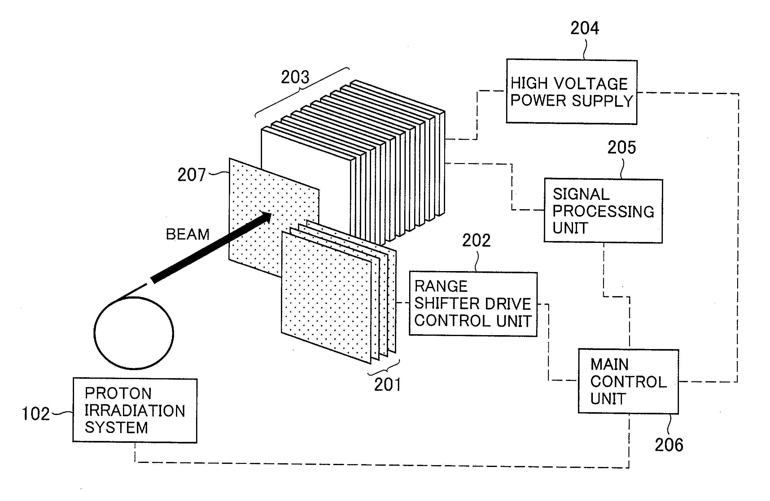
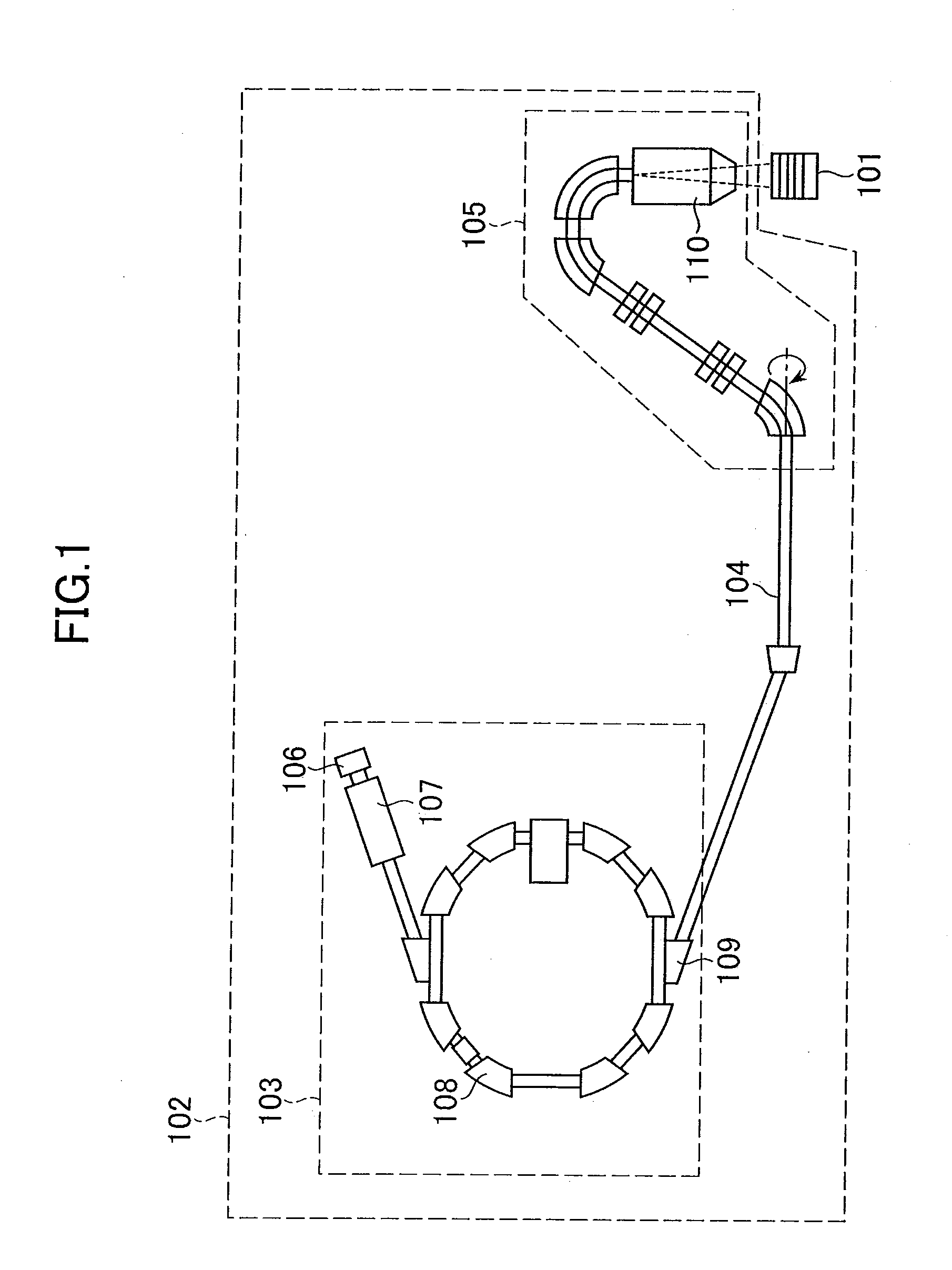
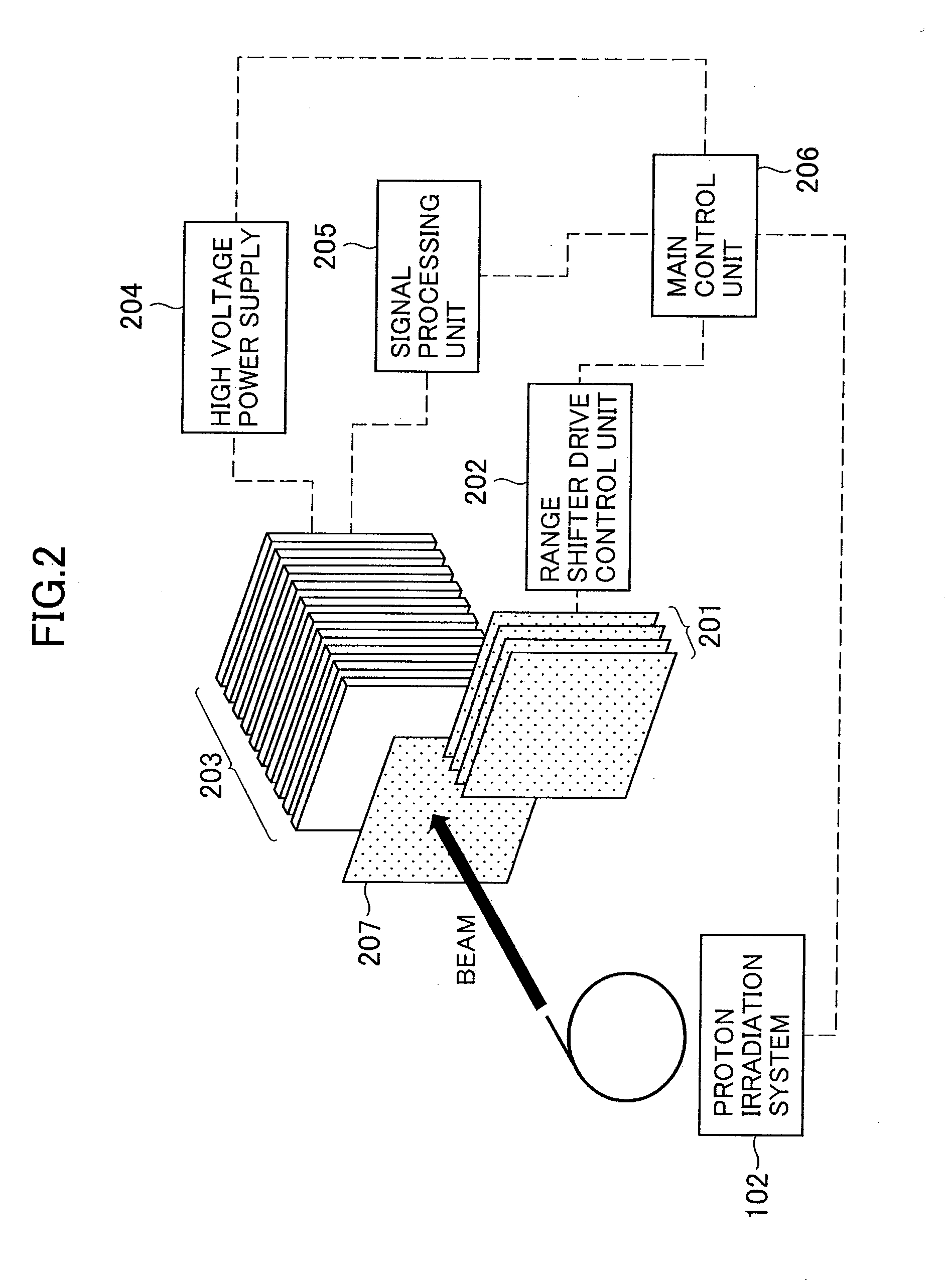
[0026]A radiation detector according to the first embodiment of the present invention is described with reference to FIG. 1. In order to conduct a performance assessment of and adjust the proton irradiation system 102 that uses a scanning method, the radiation detector 101 according to the first embodiment measures a Bragg curve that is formed in water by a beam irradiated from the proton irradiation system 102. The proton irradiation system 102 is one of radiation irradiation systems. In the present embodiment, as a radiation irradiation system, the proton irradiation system 102 is described as an example. A heavy ion irradiation system that uses a particle (carbon beam or the like) having a larger mass than a proton can be used as the radiation irradiation system. In this case, the radiation detector measures a Bragg curve that is formed in water by a heavy ion beam irradiated from the heavy ion irradiation system.
[0027]As shown in FIG. 1, the proton irradiation system 102 include...
second embodiment
[0058]Next, the radiation detector according to the second embodiment of the present invention is described.
[0059]The radiation detector 101 according to the second embodiment can measure a depth dose distribution formed in water by a scattering method. The proton irradiation system according to the second embodiment has a similar structure to the proton irradiation system 102 according to the first embodiment. Only the structure of the irradiation nozzle 110 according to the second embodiment is slightly different from that according to the first embodiment. The second embodiment is described with reference to the drawings used to describe the first embodiment.
[0060]The outline of the scattering method that is achieved by the irradiation nozzle 110 according to the present embodiment is described using a wobbling method that is a representative example of the scattering method. The irradiation nozzle 110 has the scanning magnets in the same manner as the first embodiment. In additi...
PUM
 Abstract
Description
Claims
Application Information