
Portable spray system

a spray system and portable technology, applied in the direction of ohmic resistance heating, electrical apparatus, heating element materials, etc., can solve the problems of large force, large air pressure, and large temperature sensitive performance of the material, so as to reduce power requirements, increase power transmission efficiency, and reduce power requirements

Inactive Publication Date: 2007-03-01
KOTT JOHN +1
View PDF12 Cites 46 Cited by
  • Summary
  • Abstract
  • Description
  • Claims
  • Application Information

AI Technical Summary

Benefits of technology

"The patent describes a portable spray system that uses a single power supply to power the system. The system includes two heated containers of material in fluid communication with a heated spray line and a sprayer. The system uses a low power, low pressure, and low volume compressor to mix and spray the coating materials. The material lines are wrapped with low power heaters to maintain the materials at a desirable operating temperature, while reducing power requirements. The sprayer can fit into a portable cart and the cart can fit into an elevator. The entire spraying system can run off of a single 110 volt standard power outlet. This is a significant advantage over current systems that typically use 220 volt outlets or require multiple 110 volt connections in order to work properly."

Problems solved by technology

But typical spraying equipment requires a large source of air and high air pressure.
Further, the performance of the material is very sensitive to temperature, so either large, heated rooms are typically needed in order to maintain the temperature of the materials at an operating temperature, or else high temperature heat sources are needed with smaller, enclosed areas.
Forcing these thick materials through the spray lines and spray nozzle takes a lot of force, and as a result these spray systems require large pumps, large air compressors, large heaters, and consume large amounts of electrical power.
The requirement for a 220 outlet limits the use of these sprayers, and requires long and very heavy extension cords.

Method used


Image

  • Portable spray system
  • Portable spray system
  • Portable spray system

Examples


Embodiment Construction

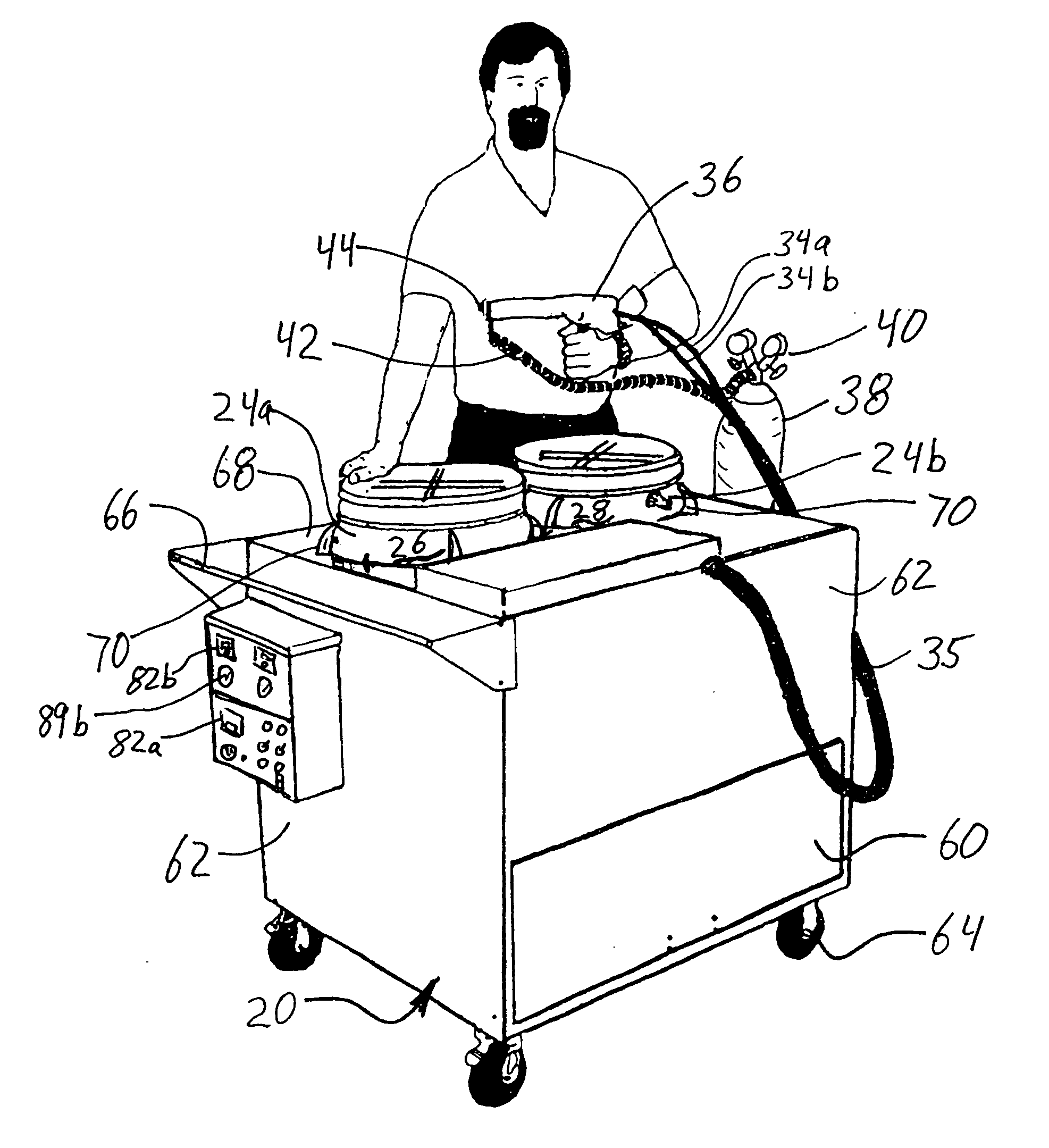
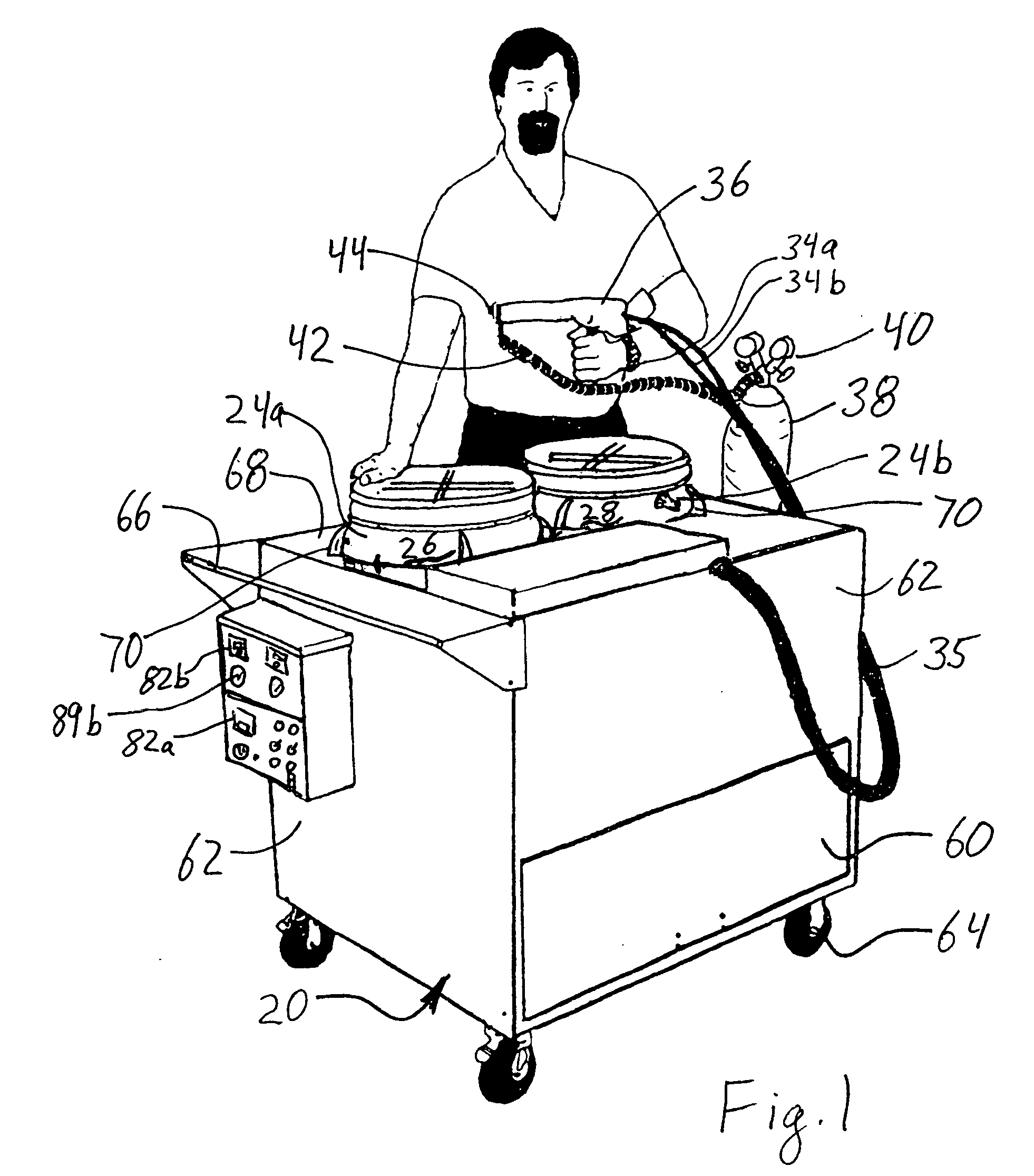
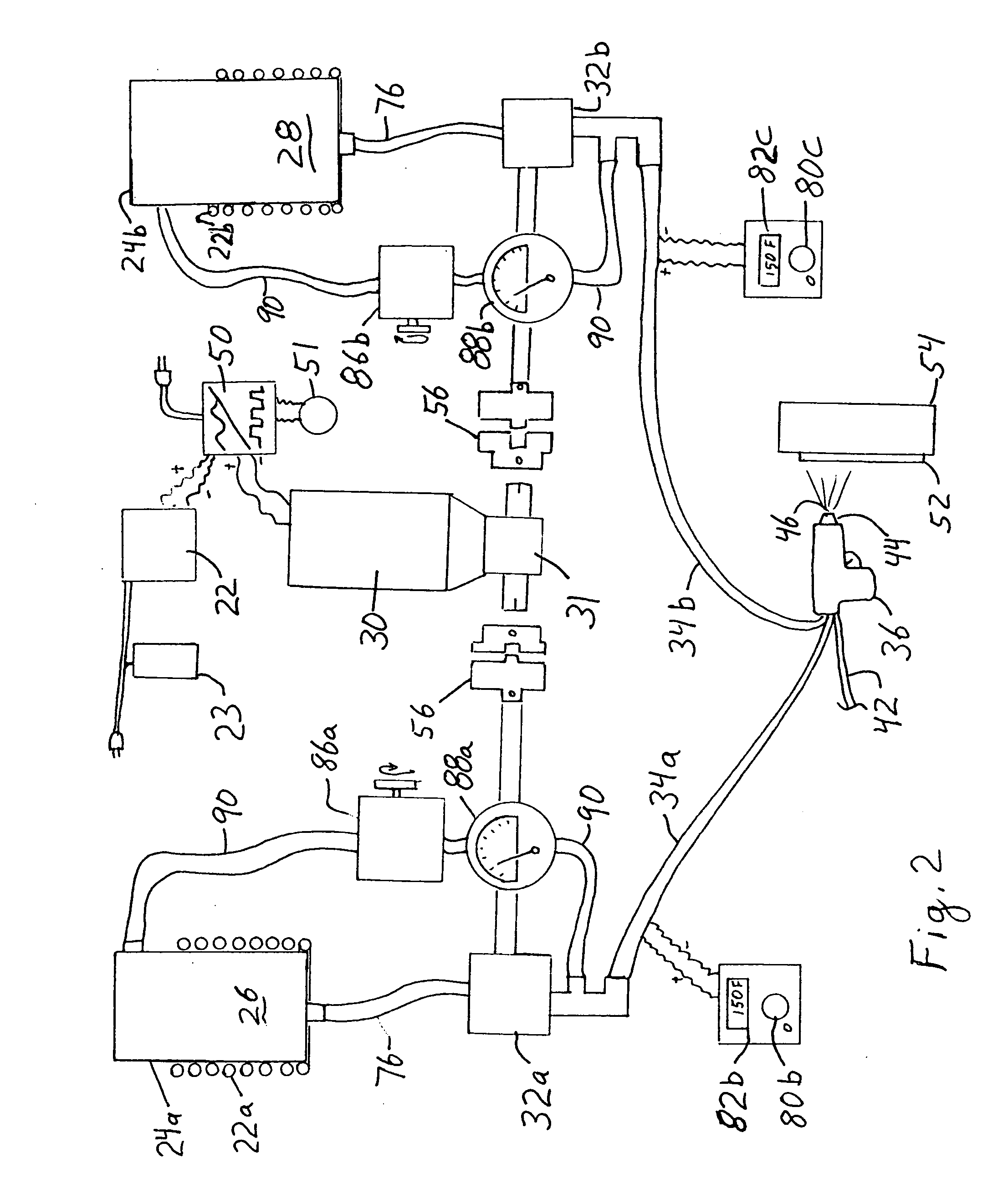
[0013] Referring to FIGS. 1-2, a portable spray system is provided that has a portable cart 20 having a temperature controlled interior provided by an auxiliary heater 22 with an adjustable thermostat 23. One or more, and typically two tanks 24 are mounted to the cart so the temperature of plural coating components can be maintained by the heater 22. There are preferably at least two tanks 24 containing plural materials for spraying. Preferably one containers 26 contains a colored resin, and one container contains an activator 28. A single motor 30 drives appropriate pumps 32 through gear drives 31 to pump the materials 26, 28 through separate material lines 34a, 34b that are connected to a spray gun 36. A resistance heater 35 is wound around at least a portion, and preferably all of the material lines 34 to keep the resin 26 and activator 28 in the lines in a flowable condition. The cart preferably carries at least one gas tank 38, such as an air bottle or nitrogen bottle, with pre...


PUM


Abstract

A portable cart is provided for spraying viscous coating material. The cart holds a resin container and an activator container, each of which is separately heated by conduction. Material transfer lines run from the containers to a spray gun, and the lines are heated. A gas tank and pressure regulator provide compressed gas to the spray gun for spraying the coating material. The spray gun is a positive displacement gun. A direct current, double stack, low-ramp motor drives two material transfer pumps to force the resin and activator through the lines to the spray gun. The two pumps are each driven through a separate helicoidal gear box. A single 110 volt AC input provides the power for the entire cart.

Description

CROSS-REFERENCE TO RELATED APPLICATION [0001] This application claims the benefit of U.S. Provisional Application No. 60 / 704,868 filed Aug. 2, 2005, the entire content of which is hereby incorporated by reference.BACKGROUND [0002] This invention relates to a method and apparatus for spraying thick, viscous materials. [0003] Thick, viscous coating materials are sprayed onto building walls, truck beds, and other items to provide a thick elastomeric coating. The sprayed material is often a plural component urethane / polyurea material. But typical spraying equipment requires a large source of air and high air pressure. Typical applications require minimum of 7 to 11 CFM at 250-3000 psi. this typically requires the use of a very large and heavy 220 volt air compressor usually weighing hundreds of pounds. Further, the performance of the material is very sensitive to temperature, so either large, heated rooms are typically needed in order to maintain the temperature of the materials at an o...

Claims


Application Information

Patent Timeline
Patent Type & Authority Applications(United States)
IPC IPC(8): H05B3/16
CPCB05B7/16B05B7/2497B05B7/166B05B7/1606
Inventor KOTT, JOHNKOTT, KENNETH
Owner KOTT JOHN
Learn More