Portable projector

a projector and portability technology, applied in the field of projectors, can solve the problems of not only a large number of optical elements, excessive installation space, and the inability to reduce the entire so as to reduce the size of the projector, minimize the space of the optical system, and minimize the path of light

Active Publication Date: 2007-03-01
LG ELECTRONICS INC
View PDF18 Cites 24 Cited by
  • Summary
  • Abstract
  • Description
  • Claims
  • Application Information

AI Technical Summary

Benefits of technology

[0019] An object of the present invention is to provide a portable projector, which includes a novel arrangement of an optical system capable of minimizing the space of the optical system, thereby achieving a reduction in the size of the projector.
[0020] Another object of the present invention is to provide a portable projector, which can minimize the path of light, thereby achieving a reduction in the loss of light.
[0021] Yet another object of the present invention is to provide a portable projector, which can achieve a stabilized arrangement of optical elements.

Problems solved by technology

The conventional projectors having the above-mentioned arrangement, however, have a problem in that they require not only a great number of optical elements, but also an excessively large installation space due to a three dimensional arrangement of an optical system.
Such an arrangement of the optical system makes it impossible to reduce the entire size of the projector.
Also, the conventional projectors generally suffer from the loss of light because a traveling path of the light from the light source to the projection lens unit is long.
Therefore, the conventional projectors have a limitation to display a bright and vivid image.
Due to the three dimensional arrangement of the optical system, furthermore, the conventional projectors have a problem in that an arrangement of optical elements is unstable.

Method used


Image

  • Portable projector
  • Portable projector
  • Portable projector

Examples


first embodiment

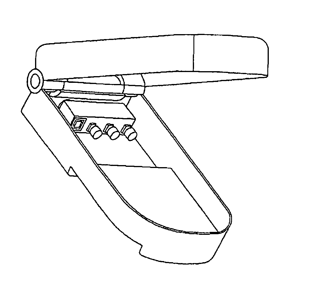
[0072]FIG. 3 is a perspective view illustrating a portable projector in accordance with the present invention.

[0073] As shown in FIG. 3, the portable projector of the present invention includes a light transmission member 50, a multi-type laser light source 51, first and second lens groups 52 and 53, and first and second multi-type scan mirrors 54 and 55.

[0074] The light transmission member 50 may be a glass member, transparent plastic member, or hollow member having an atmosphere or vacuum pressure interior. Of course, it should be understood that other materials may be used to form the light transmission member 50 so long as they have high light transmission efficiency, and the size of the light transmission member 50 may be determined based on the design of the optical system.

[0075] The light transmission member 50 may have a circular, semi-circular, triangular, or polygonal cross section as occasion demands.

[0076] In the embodiment of the present invention, the light transmis...

second embodiment

[0113]FIG. 5 is a perspective view illustrating a portable projector in accordance with the present invention.

[0114] The second embodiment of the present invention differs from the above described first embodiment of the present invention in view of the fact that one of the multi-type scan mirrors of the first embodiment is substituted by a single scan mirror.

[0115] As shown in FIG. 5, the projector according to the second embodiment of the present invention includes a light transmission member 60, a multi-type laser light source 61, first and second lens groups 62 and 63, a mirror 64, and a multi-type scan mirror 65.

[0116] Here, the multi-type scan mirror 65 may use a galvano mirror scanning incident light beams in a two dimensional manner.

[0117] The other configurations and operation of the second embodiment are similar to those of the first embodiment, and no detailed description thereof will be given.

[0118] The portable projector in accordance with the present invention havi...

third embodiment

[0119]FIG. 7 is a perspective view illustrating a portable projector in accordance with the present invention.

[0120] As shown in FIG. 7, the projector according to the third embodiment of the present invention includes a light transmission member 80, a multi-type laser light source 81, first, second, and third lens groups 82, 83, and 84, first and second mirror groups 85 and 86, first, second, and third diffraction lenses 87, 88, and 89, and a scan mirror 90.

[0121] Here, the light transmission member 80 is equal to that of the above described first embodiment of the present invention, and no detailed description thereof will be given.

[0122] In accordance with the design of the portable projector, of all the surfaces of the light transmission member 80, certain surface regions where the first, second, and third lens groups 82, 83, and 84, first and second mirror groups 85 and 86, first, second, and third diffraction lenses 87, 88, and 89, and scan mirror 90 are supported may be rai...


PUM


Abstract

A portable projector is disclosed. The portable projector comprises a light transmission member having first and second surfaces, a multi-type laser light source including a plurality of sub laser light sources for emitting light beams onto the first surface of the member based on an external image signal, so as to allow the light beams to be transmitted into the member, one or more optical elements supported on at least one of the first and second surfaces of the member for diffracting and reflecting the light beams incident from the multi-type laser light source into the member, and at least one multi-type scan mirror supported on one of the first and second surfaces of the member for scanning the light beams diffracted and reflected from the optical elements onto an external screen located at the outside of the member, based on an external control signal.

Description

[0001] This application claims the benefit of the Korean Patent Application No. P2005-80896 filed on Aug. 31, 2005, No. P2005-86431 filed on Sep. 15, 2005 and p2005-91338 filed on Sep. 29, 2005, which is hereby incorporated by reference as if fully set forth herein. BACKGROUND OF THE INVENTION [0002] 1. Field of the Invention [0003] The present invention relates to a projector, and more particularly, to a portable projector. [0004] 2. Discussion of the Related Art [0005] The recent tendency of display devices is to provide a large screen size as well as lightness and thinness. Of such display devices, projectors have been greatly highlighted because they can realize a large screen of 100 inches or more. [0006] Such a projector is a display device which projects an image generated from a micro device such as a liquid crystal display (LCD) panel, a reflective liquid crystal on silicon (LCoS) panel, or a digital micro-mirror device (DMD) panel, onto a screen, thereby displaying the ima...

Claims


Application Information

Patent Timeline
Patent Type & Authority Applications(United States)
IPC IPC(8): G03B21/22
CPCG02B26/101G02B26/105H04N5/7416H04M1/22H04M2250/16H04M1/0272
Inventor SHIN, SUNG CHUL
Owner LG ELECTRONICS INC
Why Eureka
Try Eureka