
Coordinate measuring device

a technology of measuring device and coordinate, which is applied in the direction of measurement device, optical device, instruments, etc., can solve the problems of no longer being able to meet the more stringent requirements as to the accuracy of measurement, and being virtually impossible to create a hermetically airtight, so as to reduce the effect of environmental parameters on the change in the wavelength of light beam

Inactive Publication Date: 2007-03-01
VISTEC SEMICON SYST
View PDF16 Cites 7 Cited by
  • Summary
  • Abstract
  • Description
  • Claims
  • Application Information

AI Technical Summary

Benefits of technology

[0008] It is therefore an object of the present invention to provide a reference-beam interferometer, wherein the effect of environmental parameters on the change in the wavelength of the light beam is further minimized.

Problems solved by technology

It is also virtually impossible to create with reasonable efforts a hermetically airtight, in particular pressure-sealed chamber, in particular because it is necessary to exchange the measuring objects easily and rapidly.
A drawback of the present state of the art lies in the fact that it is no longer able to fulfill the more stringent requirements as to the accuracy of the measurement.

Method used


Image

  • Coordinate measuring device
  • Coordinate measuring device

Examples


Embodiment Construction

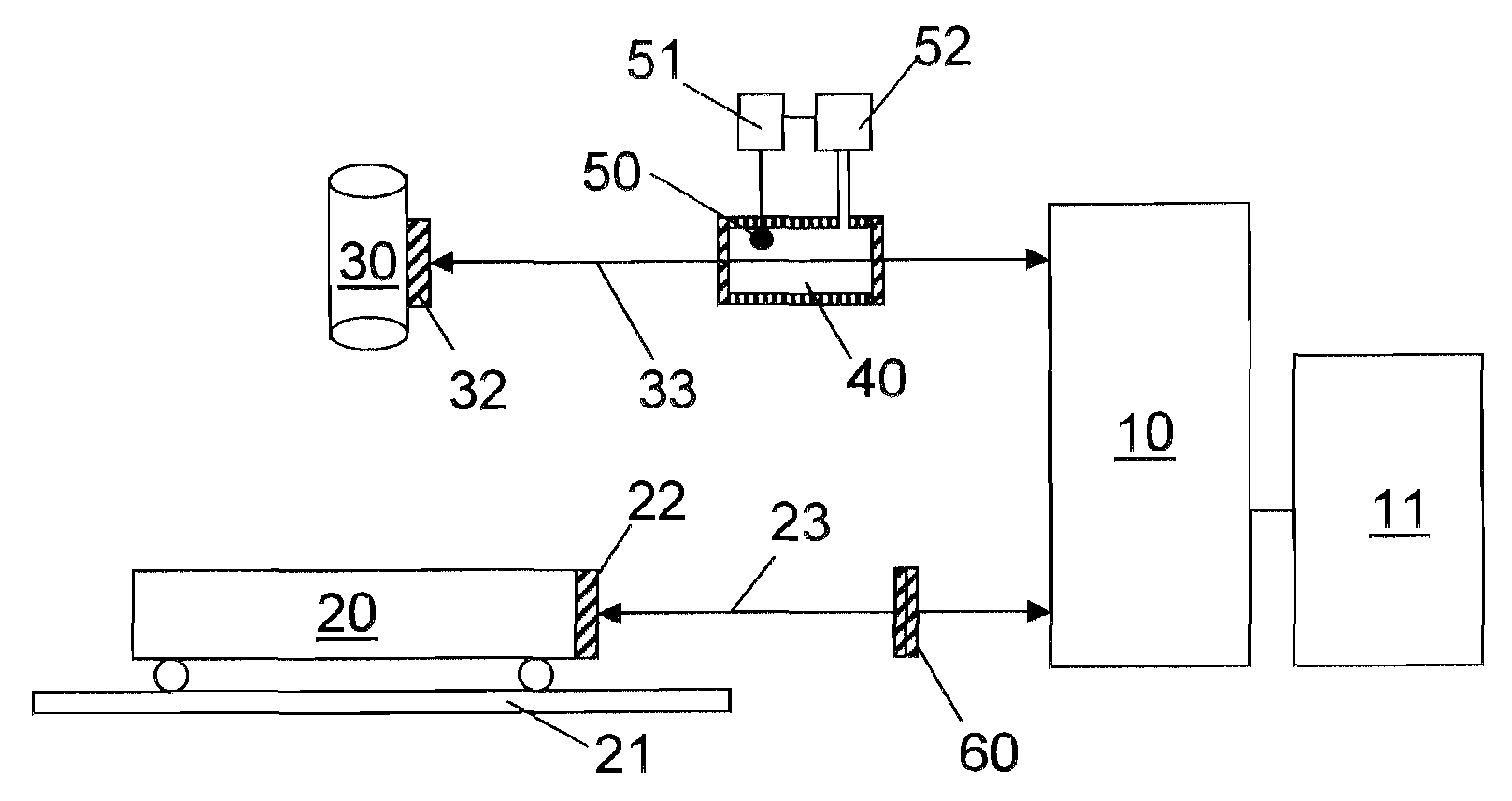
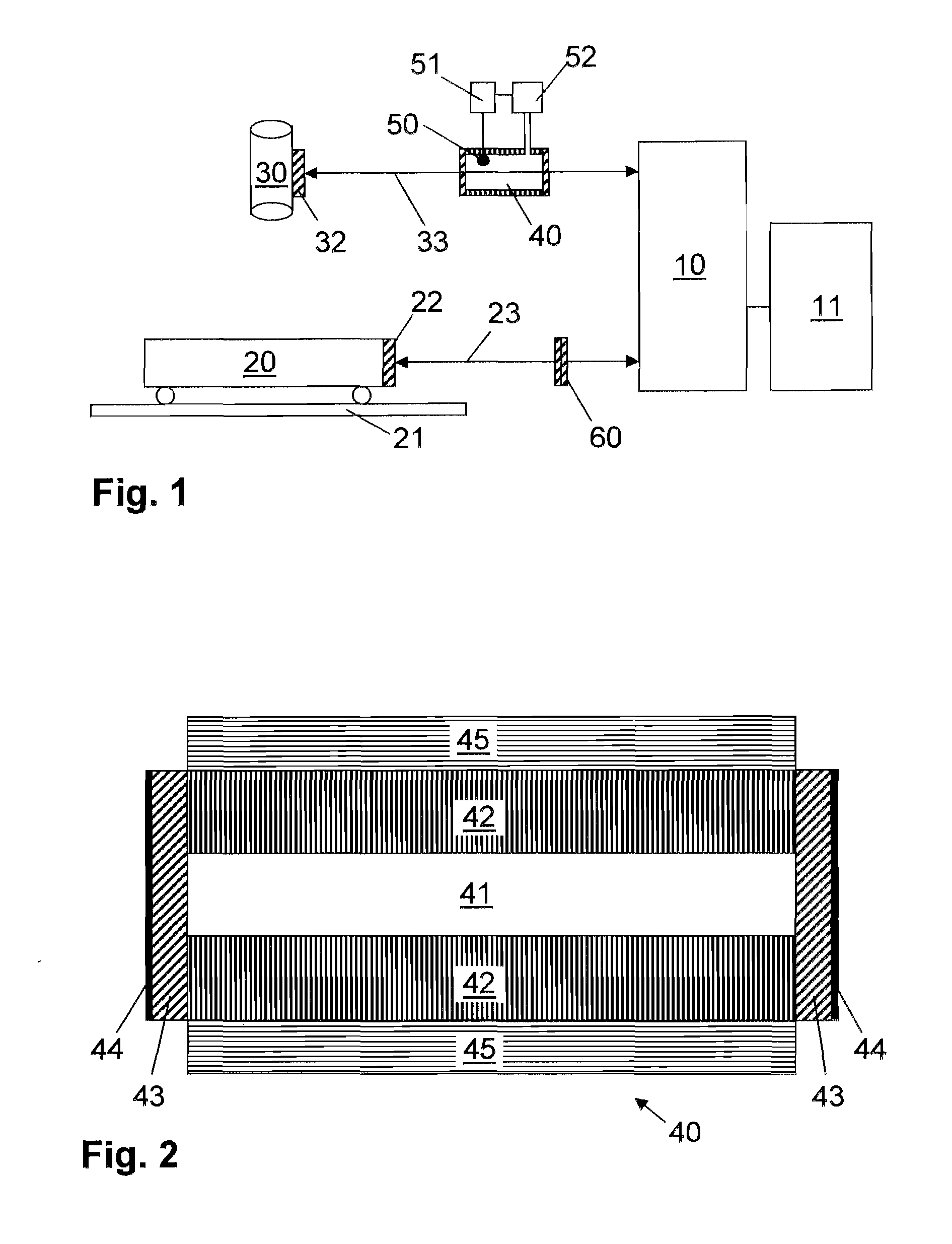
[0031]FIG. 1 shows a coordinate measuring device with a reference-beam interferometer 10 together with its reference beam path 33 and its measuring beam path 23. Measuring beam 23 impinges on measuring mirror22, which is attached on traversable stage 20. Stage 20 is traversable with respect to a fixed base 21 and carries the measuring object (not shown). Reference beam 33 impinges on reference mirror 32, which is attached on the fixed lens assembly 30. Lens assembly 30 is focused on a measuring point on the measuring object placed on the traversable stage. In the measuring process the measuring object on the traversable stage is sufficiently moved by the latter so that the lens assembly focuses on another measuring point. The distance between the two measuring points is measured by the reference-beam interferometer as a distance variation of the traversable stage with respect to the lens assembly. Reference-beam interferometer 10 is coupled to a position determining means 11 for eva...


PUM


Abstract

The present invention relates to a reference-beam interferometer for determining the position of a traversable stage, wherein an evacuated tube is inserted into the longer of the two interferometer legs. The tube is closed off by windows, which have a negative coefficient of thermal expansion and which can have a coating for reflecting heat radiation. Moreover, thermal compensation plates are inserted into the shorter of the two beam paths.

Description

RELATED APPLICATIONS [0001] This patent application claims priority of German Patent Application No. 10 2005 040 661.0, filed on Aug. 26, 2005, which is incorporated herein by reference. FIELD OF THE INVENTION [0002] The present invention relates to a coordinate measuring device for determining the position of a traversable stage, wherein the position determination is carried out by an interferometer and wherein different path lengths of the measuring and reference beam paths in the interferometer are compensated by a light-transmitting, closed, incompressible body. BACKGROUND OF THE INVENTION [0003] Reference-beam interferometers are used for high-precision distance and position measurements and are, for example, an essential component of masks and wafer measuring apparatus for the semiconductor industry. To measure structures of current highly integrated circuits, these devices have a precision in the range of a few nanometers. [0004] In the high-precision interferometric measurem...

Claims


Application Information

Patent Timeline
Patent Type & Authority Applications(United States)
IPC IPC(8): G01B11/02
CPCG03F7/70775G01B9/02058G01B11/026G03F7/70883
Inventor HEIDEN, MICHAELBOESSER, HANS-ARTHUR
Owner VISTEC SEMICON SYST
Learn More