Method and apparatus for enforcing of power control in a blade center chassis

Inactive Publication Date: 2007-03-01
IBM CORP
View PDF7 Cites 62 Cited by
  • Summary
  • Abstract
  • Description
  • Claims
  • Application Information

AI Technical Summary

Benefits of technology

[0011] Thus, another object of the present invention is to protect blade servers in a blade center chassis from the adverse effects of a malfunctioning or defective blade server, such as total loss of power in the blade center chassis due to overloading the common power supply or from exposure to excessive thermal loading.
[0012] Still another object of the present invention is to provide for the secure and reliable operation of blade servers in a blade center chassis by providing fault-tolerance for the adverse effects of

Problems solved by technology

Even though power consumption and device complexity per unit of processing power may actually decrease with a blade center, since the physical density of the computing devices has increased, the demands on power consumption for processing power and cooling have also intensified as overall computing power has increased.
If any blade exceeds its allocation, it can force the entire chassis to exceed threshold values, which can, in turn, force the common power supply to shut down, causing other blades to be turned off.
Another risk is that any blade exceeding its allocation can cause other blades to shut down due to temperatures exceeding their critical thresholds.
Pro

Method used


Image

  • Method and apparatus for enforcing of power control in a blade center chassis
  • Method and apparatus for enforcing of power control in a blade center chassis
  • Method and apparatus for enforcing of power control in a blade center chassis

Examples


Embodiment Construction

[0026] In the following description, numerous specific details are set forth such as specific word or byte lengths, etc. to provide a thorough understanding of the present invention. However, it will be obvious to those skilled in the art that the present invention may be practiced without such specific details. In other instances, well-known circuits have been shown in block diagram form in order not to obscure the present invention in unnecessary detail. For the most part, details concerning timing considerations and the like have been omitted inasmuch as such details are not necessary to obtain a complete understanding of the present invention and are within the skills of persons of ordinary skill in the relevant art.

[0027] Refer now to the drawings wherein depicted elements are not necessarily shown to scale and wherein like or similar elements are designated by the same reference numeral through the several views.

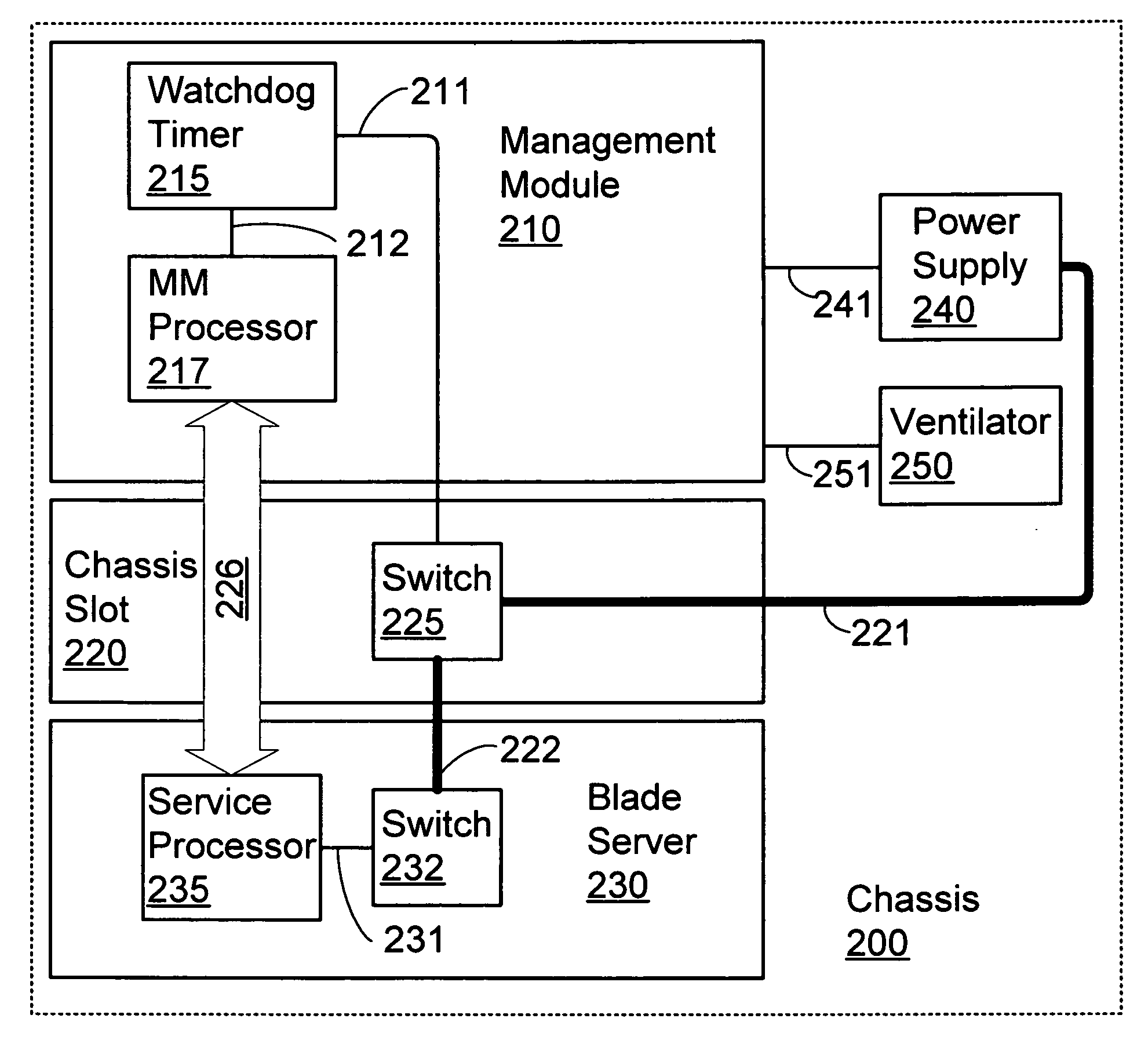
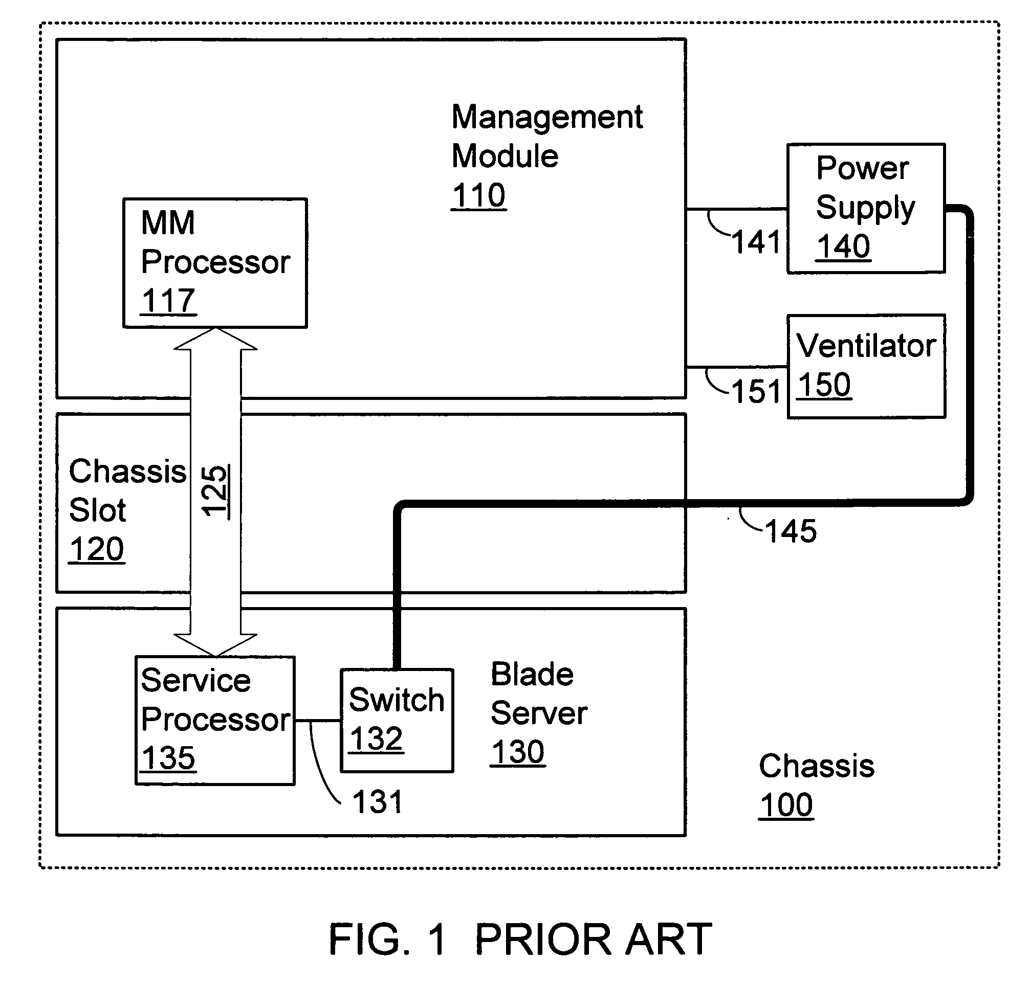
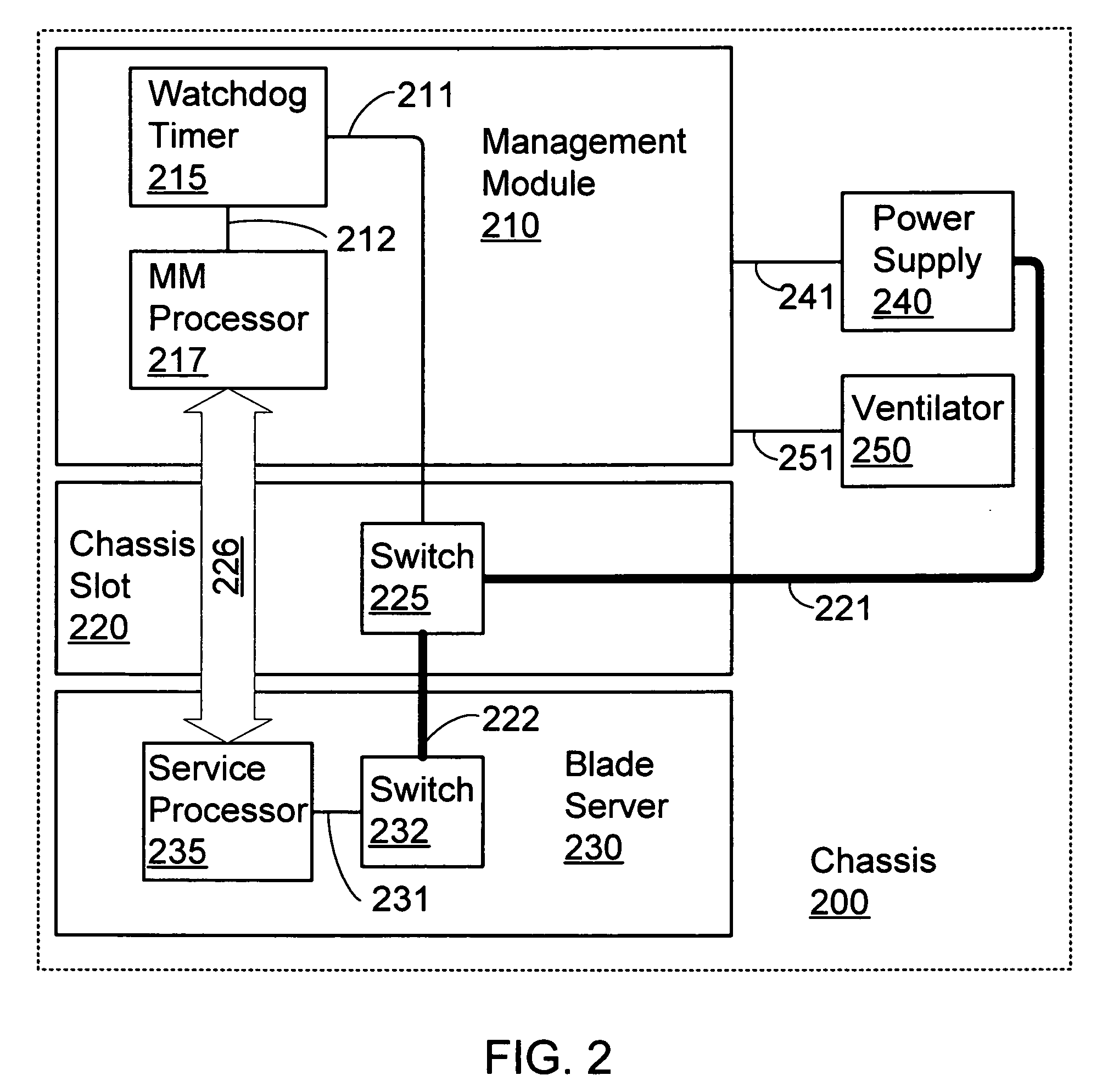
[0028] The prior art system components and architecture for con...


PUM


Abstract

A mechanism for changing ownership over the physical power to a blade server in a blade center chassis that prevents a malfunctioning blade from jeopardizing other components in the chassis. When the management module is not present, control over power to the blade is switched to a service processor on the blade. This arbitration of control over power to a blade is accomplished by implementing a watchdog timer mechanism. The management module is responsible for tickling the watchdog timer when the present in the chassis and operating normally. This mechanism provides the management module with control over power. If the management module malfunctions or is removed, control over power is switched to the local service processor on the blade server as soon as the watchdog timer is not tickled.

Description

TECHNICAL FIELD [0001] The present invention relates in general to data processing systems, and in particular, to communications network devices referred to as blade servers. BACKGROUND INFORMATION [0002] The use of servers as devices within communications networks is well known in the art. A server is equipment that makes available file, database, printing, facsimile, communications or other services to client terminals / stations with access to the network the server serves. When the server permits client / terminal station access to external communications network it is sometimes known as a gateway. Servers are available in different sizes, shapes and varieties. Servers may be distributed throughout a network or they may be concentrated in centralized data centers. [0003] Advances in centralized data processing centers have resulted in smaller form factors for server devices and an increase in the density of processing units, thereby reducing space requirements for computing infrastr...

Claims


Application Information

Patent Timeline
IPC IPC(8): G06F1/16
CPCG06F1/206H05K7/20836G06F1/26
Inventor MERKIN, AARON E.BREY, THOMAS M.BOLAN, JOSEPH E.
Owner IBM CORP
Why Eureka
Try Eureka