
Light guide plate having two micro structures and back light unit having the light guide plate

Inactive Publication Date: 2007-03-01
IND TECH RES INST
View PDF8 Cites 29 Cited by
  • Summary
  • Abstract
  • Description
  • Claims
  • Application Information

AI Technical Summary

Benefits of technology

[0016] It is another objective of the present invention to provide a light guide plate and a back light unit having the light guide plate which have a tunable composite optical effect with light collection and diffusion functions so as to increase brightness and evenness of exit light.
[0032] Compared with the prior art, the light guide plate which provides functions of light diffusion and light collection has a capability to regulate exit light distribution and exit light intensity by use of optical designability and controllability of the first and second micro structure according to the present invention. Meanwhile, the first micro structure has a tunable composite optical effect with light collection and diffusion functions so as to increase brightness and evenness of the exit light, and the second micro structure has a design of curved face for destroying total reflection of light, such that bright lines can be effectively prevented from occurrence by avoiding light outputting from the direction over against the first optical face. Therefore, the problems of the prior art can be solved.

Problems solved by technology

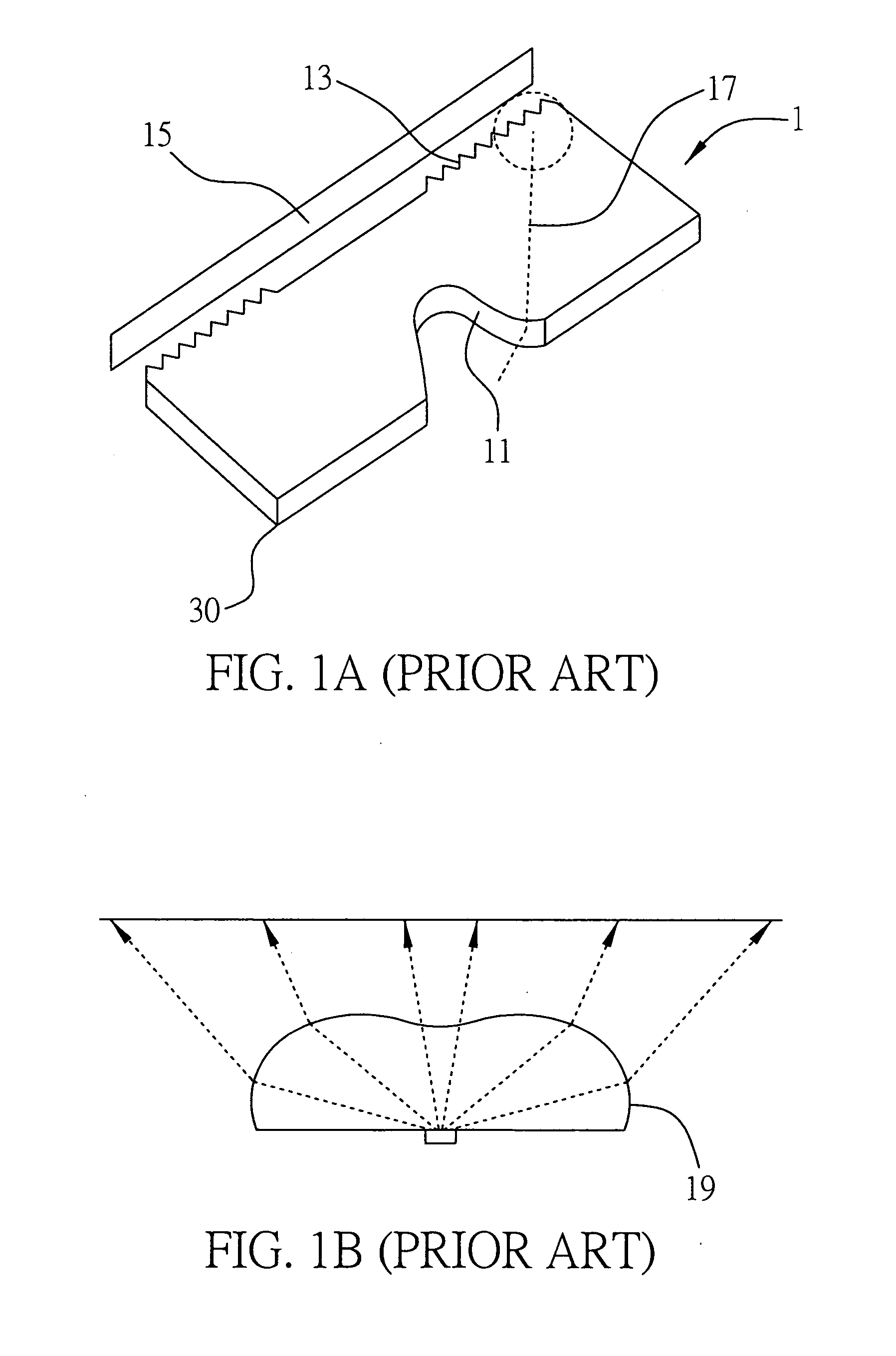
Accordingly, such technique not only is useless to industry value, but also has high cost for its hard fabrication.
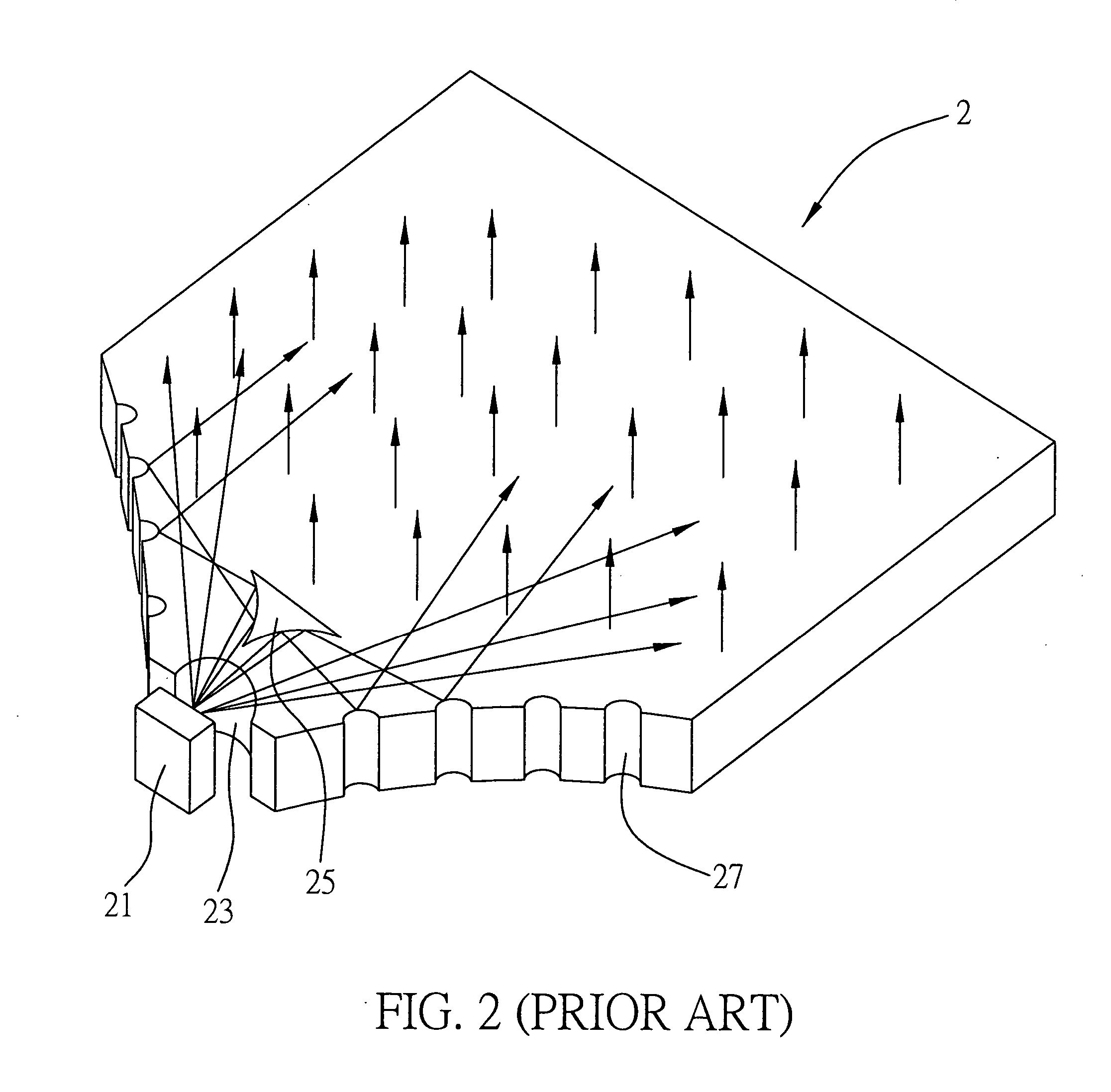
However, great loss of energy may be caused to reduce energy of the exit light in the above U.S. Pat. No. 6,139,163 as much reflection and refraction of the light must be performed before inputting the light inside the light guide plate.
Furthermore, it is hard in practical fabrication because the structure is complicated and economic effect still can not be estimated.
Such micro structure on the top surface of the light guide plate has light collection function but has not diffusion function, and the evenness effect of the exit light is still not good.

Method used


Image

  • Light guide plate having two micro structures and back light unit having the light guide plate
  • Light guide plate having two micro structures and back light unit having the light guide plate
  • Light guide plate having two micro structures and back light unit having the light guide plate

Examples


first embodiment

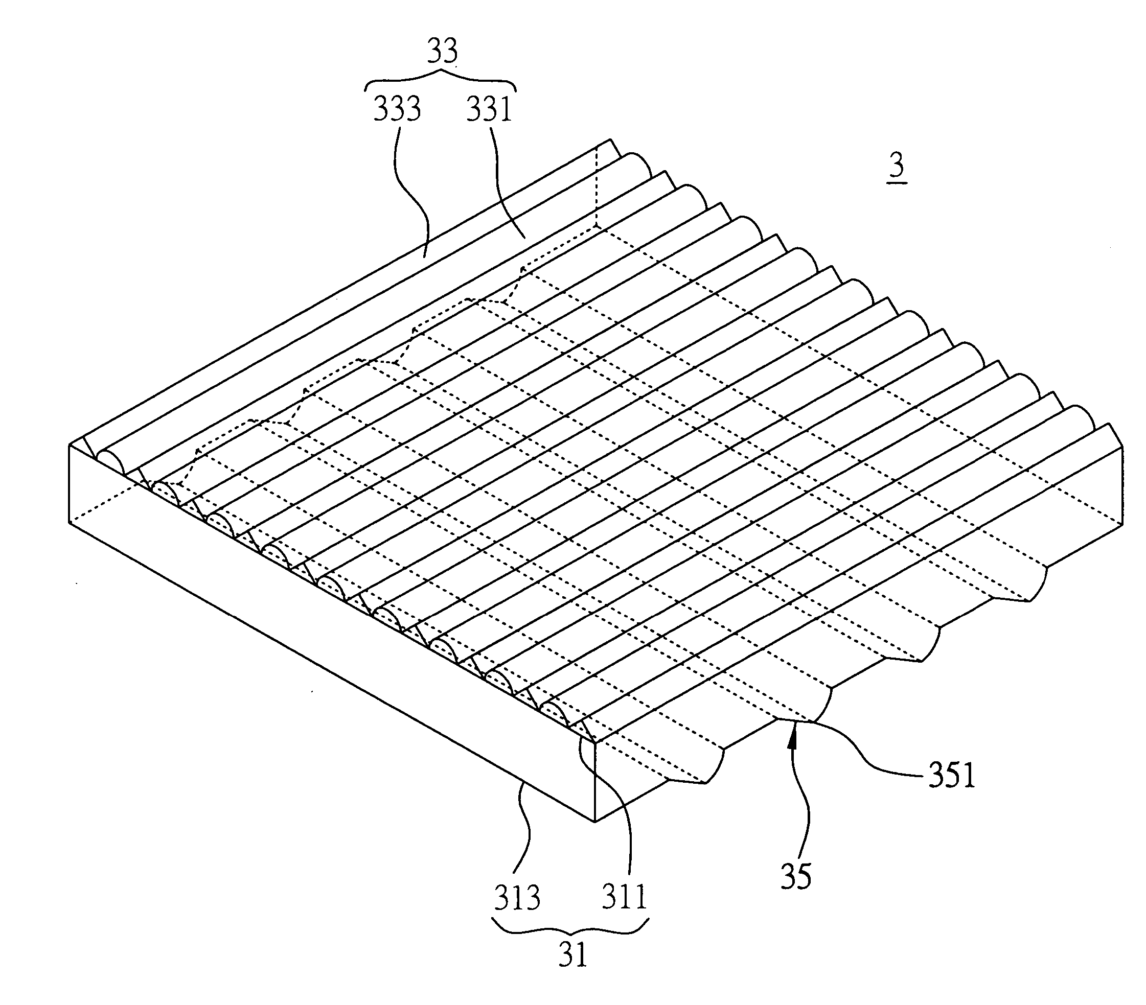
[0052]FIG. 3A to FIG. 8B are views showing a structure of a light guide plate 3 and a back light unit having the light guide plate of a first embodiment according to the present invention.

[0053] Please refer to FIG. 3A, which is a sectional view showing the light guide plate 3 of the present embodiment. The light guide plate 3 comprises a transparent substrate 31, a first micro structure 33 and a second micro structure 35 (shown in FIG. 7).

[0054] As shown in FIG. 3A, the transparent substrate 31 has a first optical face 311 and a second optical face 313 opposed to the first optical face 311. In this embodiment, the transparent substrate 31 is a transparent substrate and the like.

[0055] The first micro structure 33 is formed on the first optical face 311 and is made of transparent material. The first micro structure 33 comprises a plurality of light diffusion portions 331 installed in parallel to each other for diffusing light (exit light), and a plurality of light collection port...

second embodiment

[0068]FIG. 9 is a sectional view showing a light guide plate and a back light unit having the light guide plate according to a second embodiment of the present invention. The components which are the same as or similar to those of the first embodiment are represented by the same or similar reference numbers and the detailed descriptions of these components are omitted in order to make the disclosure of the present invention easier to be understood.

[0069] The difference of the light guide plate between the second embodiment and the first embodiment is that, the first micro structure of the second embodiment has at least a light diffusion and collection composite portion, in instead of the light diffusion portions and the light collection portions, which are comprised in the light guide plate of the first embodiment.

[0070] As shown in FIG. 9, the light guide plate 3 comprises a transparent substrate 31, a first micro structure 33 and a second micro structure 35. The structure of the...

third embodiment

[0073]FIG. 10 is a sectional view showing a light guide plate and a back light unit having the light guide plate according to a third embodiment of the present invention. The components which are the same as or similar to those of the above embodiment are represented by the same or similar reference numbers and the detailed descriptions of these components are omitted.

[0074] The difference between the third embodiment and the above embodiment is that the first micro structure has a plurality of light diffusion and collection composite portions and light collection portions parallel to each other.

[0075] Referring to FIG. 10, the first micro structure 33 of the light guide plate 3 comprises a plurality of light diffusion and collection composite portions 335 and light collection portions 333 parallel to each other for providing functions of light diffusion and light collection. As described in the above embodiment, each of the light diffusion and collection composite portions 335 ha...


PUM


Abstract

A light guide plate is provided. The light guide plate has a transparent substrate having a first optical face and a second optical face, a first micro structure and a second micro structure respectively corresponding to the first optical face and the second optical face. The first micro structure has a tunable composite optical effect with light collection and diffusion functions so as to increase brightness and evenness of exit light. The second micro structure has a design of curved face to destroy total reflection of light, such that bright lines can be effectively prevented from occurrence by avoiding the light outputting from the direction over against the first optical face. A back light unit having the light guide plate is further provided in the present invention.

Description

BACKGROUND OF THE INVENTION [0001] 1. Field of the Invention [0002] The present invention relates to an optical modulation technique and, more particularly to a light guide plate having two micro structures and a back light unit having the light guide plate. [0003] 2. Descriptions of Related Arts [0004] Recently, digital products in new generation not only can integrate technique of information, consumption and communication fields, but also has good multimedia performance with the rapid development of related technical fields. Moreover, an image processing technique has become a notable development art with maturation of accessory art and application increment. Thus, demands of various digital products having display function especially LCD are becoming more and more important. According to the estimate of Display Search, the amounts of future LCD TV will reach to 16240 thousand in 2006 at high requests; thereby another business in critical accessories of LCD will come forth, where...

Claims


Application Information

Patent Timeline
IPC IPC(8): F21V7/04
CPCG02B6/0061G02B6/0038
Inventor YAO, PO-HUNGPAO, YU-NANSUN, YI-TINGLIN, BEN-SHENGLIN, TSUNG-HSIN
Owner IND TECH RES INST
Learn More