
Fluidic mixing structure, method for fabricating same, and mixing method

a technology of mixing structure and fluidic system, applied in the field of micromixers, can solve the problems of complex and expensive integration of microfluidic system, difficult to achieve rapid and complete mixing, and compromise low power

Inactive Publication Date: 2007-03-01
TELEDYNE LICENSING
View PDF37 Cites 40 Cited by
  • Summary
  • Abstract
  • Description
  • Claims
  • Application Information

AI Technical Summary

Problems solved by technology

Flow mixing in microfluidic devices presents a challenge as a consequence of low Reynolds numbers where parallel laminar flow dominates tending to prevent mass transfer across separate flow stream boundaries.
Instead, flow mixing is dominated by liquid particle diffusion making rapid and complete mixing difficult to achieve.
These conventional approaches compromise low power, compact operation.
Active micromixers usually require external power sources and accessories the integration of which into a microfluidic system is complicated and expensive.

Method used


Image

  • Fluidic mixing structure, method for fabricating same, and mixing method
  • Fluidic mixing structure, method for fabricating same, and mixing method
  • Fluidic mixing structure, method for fabricating same, and mixing method

Examples


Embodiment Construction

[0028] The following description presents preferred embodiments of the invention representing the best mode contemplated for practicing the invention. This description is not to be taken in a limiting sense but is made merely for the purpose of describing the general principles of the invention whose scope is defined by the appended claims.

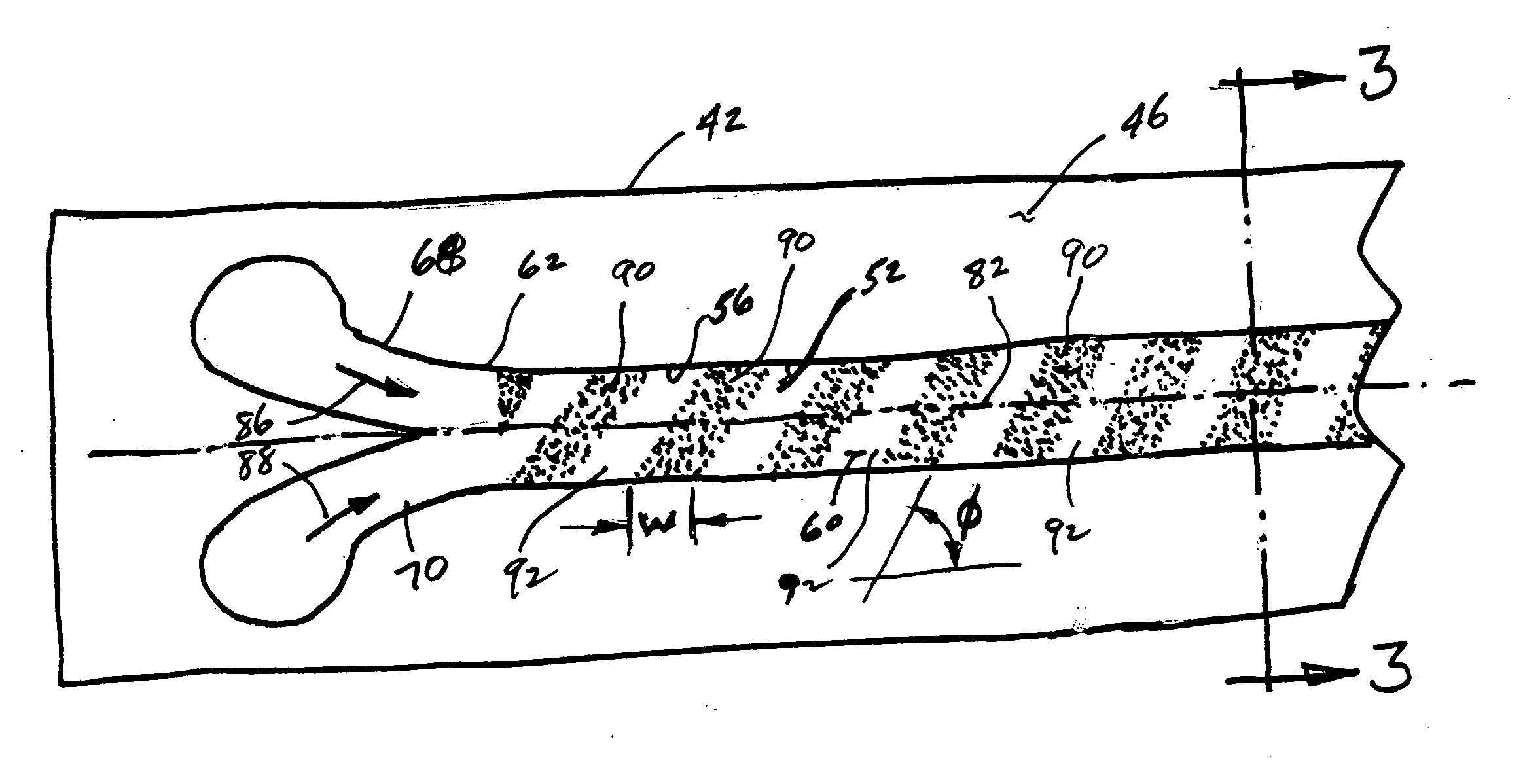
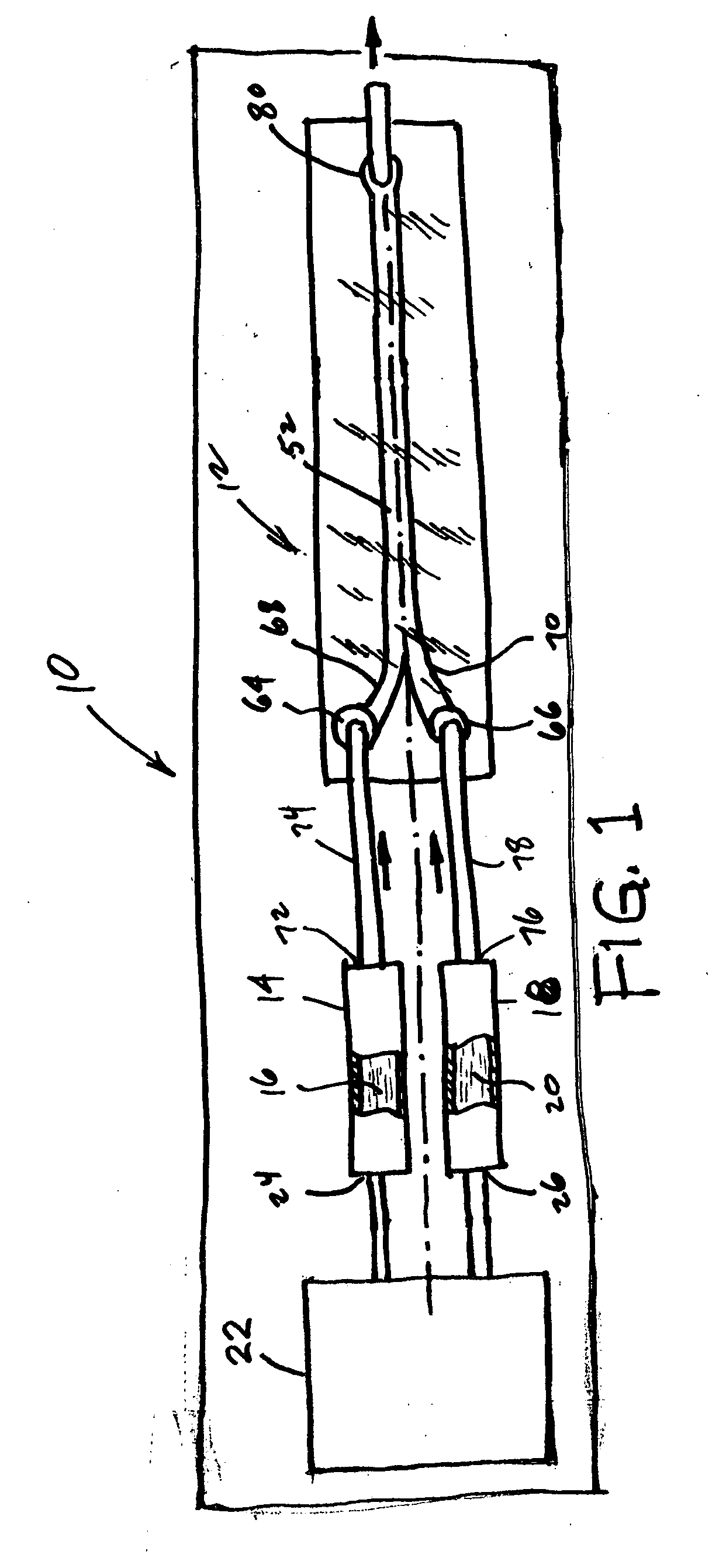
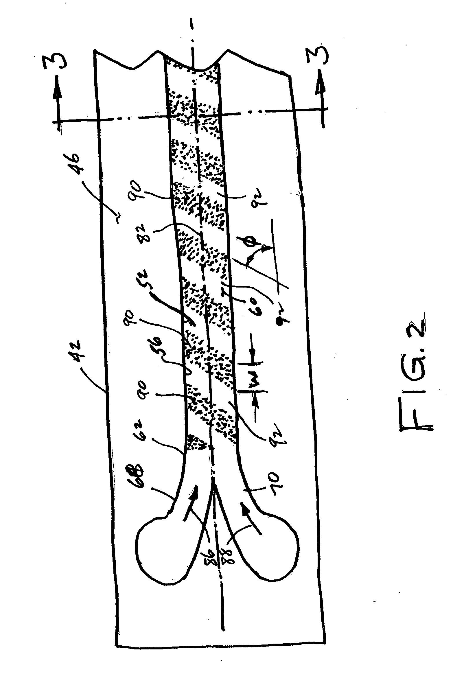
[0029]FIG. 1 shows a micromixer system 10 in accordance with one specific, preferred embodiment of the present invention. The micromixer system 10 is designed to mix two liquids supplied to a micromixer 12 from a first reservoir 14 containing a first liquid 16 and a second reservoir 18 containing a second liquid 20. The system further comprises a pump 22 for generating flow of the first and second liquids from the reservoirs 14 and 18 into the micromixer 12. Numerous techniques for generating fluid flow and pumping in microfluidic devices are available, and are well-known to those skilled in the art as exemplified by those described in “MEMS-Micr...


PUM


Abstract

A fluidic micromixer comprises a plurality of fluid inlets in communication with a mixing chamber, the plurality of fluid inlets being adapted to introduce into the chamber a corresponding plurality of distinct fluid streams. The mixing chamber comprises at least one surface patterned to define hydrophobic and hydrophilic regions spaced apart along a principal direction of fluid flow within the chamber from the fluid inlets to a fluid outlet, the regions being adapted to induce fluid flow in a direction transverse to the principal direction of fluid flow to mix the fluid streams. At least one of the hydrophobic regions may comprise microstructures patterned on the at least one surface. Also disclosed are a method for fabricating the micromixer, a method of mixing a plurality of fluid streams by vortex mixing or instability mixing, and a system comprising the micromixer, fluid reservoirs and a pump for generating flow of fluids from the reservoirs to the micromixer.

Description

CROSS REFERENCE TO RELATED APPLICATION [0001] This application claims the benefit of U.S. Provisional Application No. 60 / 711,539 filed on Aug. 25, 2005.BACKGROUND OF THE INVENTION [0002] 1. Field of the Invention [0003] The present invention relates generally to micromixers used in microfluidic systems, and particularly to a micromixer that induces adequate mixing while eliminating the need for a long mixing chamber or obstructions therein. The invention further relates to a method for fabricating micromixers and to a method for mixing fluid streams. [0004] 2. Description of the Related Art [0005] In microfluidics systems, microscale fluid mixing is essential for successfully performing on-chip chemical analysis and biochemical processes such as drug delivery, sequencing of nucleic acids, DNA hybridization, cell activation, protein folding, enzyme reactions and PCR amplification. [0006] Flow mixing in microfluidic devices presents a challenge as a consequence of low Reynolds numbers...

Claims


Application Information

Patent Timeline
IPC IPC(8): B81B1/00
CPCB01F13/0084B81C1/00206B01F13/0086B01F33/30352B01F33/30351
Inventor DENATALE, JEFFREY F.CHEN, CHUNG-LUNGCAI, QINGJUNTSAI, CHIALUN
Owner TELEDYNE LICENSING
Learn More