Explicit flow control in Gigabit/10 Gigabit Ethernet system

a flow control and ethernet technology, applied in the field of network communication, can solve the problems of memory latency (in reading packets for transmission or writing packets that have been received) and the current ethernet standard not allowing the interruption of transmission of packets

Inactive Publication Date: 2007-03-01
APPLE INC
View PDF13 Cites 18 Cited by
  • Summary
  • Abstract
  • Description
  • Claims
  • Application Information

AI Technical Summary

Benefits of technology

[0010] In one embodiment, a system comprises a communication medium; a first controller coupled to the communication medium; and a second controller coupled to the communication medium. The first controller is configured to interrupt transmission of a packet on the communication medium to the second controller subsequent to transmission of a first portion of the packet. The first controller is configured to transmit at least one control symbol on the communication medium in response to interrupting transmission of the packet, and wherein the first controller is configured to continue transmission of the packet with a second portion of the packet.
[0011] In another embodiment, a controller is configured to communicate packets on a communication medium. The controller comprises a media access controller (MAC) configured to transmit a packet as a plurality of bytes and a physical coding sublayer (PCS) circuit coupled to receive the plurality of bytes from the MAC. The PCS circuit is configured to encode each byte as a respective data symbol for transmission on the communication medium. The MAC is configured to interrupt transmission o...

Problems solved by technology

The Ethernet standard currently does not permit the interruption of transmission of a packet.
As the bandwidth of the network interfaces has increased, the likelihood that other factors in a system become bottlenecks to transmission has also increased.
For example, memory latency (in reading packets for transmission or writing packets that have been received) can become an issue.
Memory latency on the transmit side to read the packet from memory may be an issue since the packet may not be read q...

Method used


Image

  • Explicit flow control in Gigabit/10 Gigabit Ethernet system
  • Explicit flow control in Gigabit/10 Gigabit Ethernet system
  • Explicit flow control in Gigabit/10 Gigabit Ethernet system

Examples


Embodiment Construction

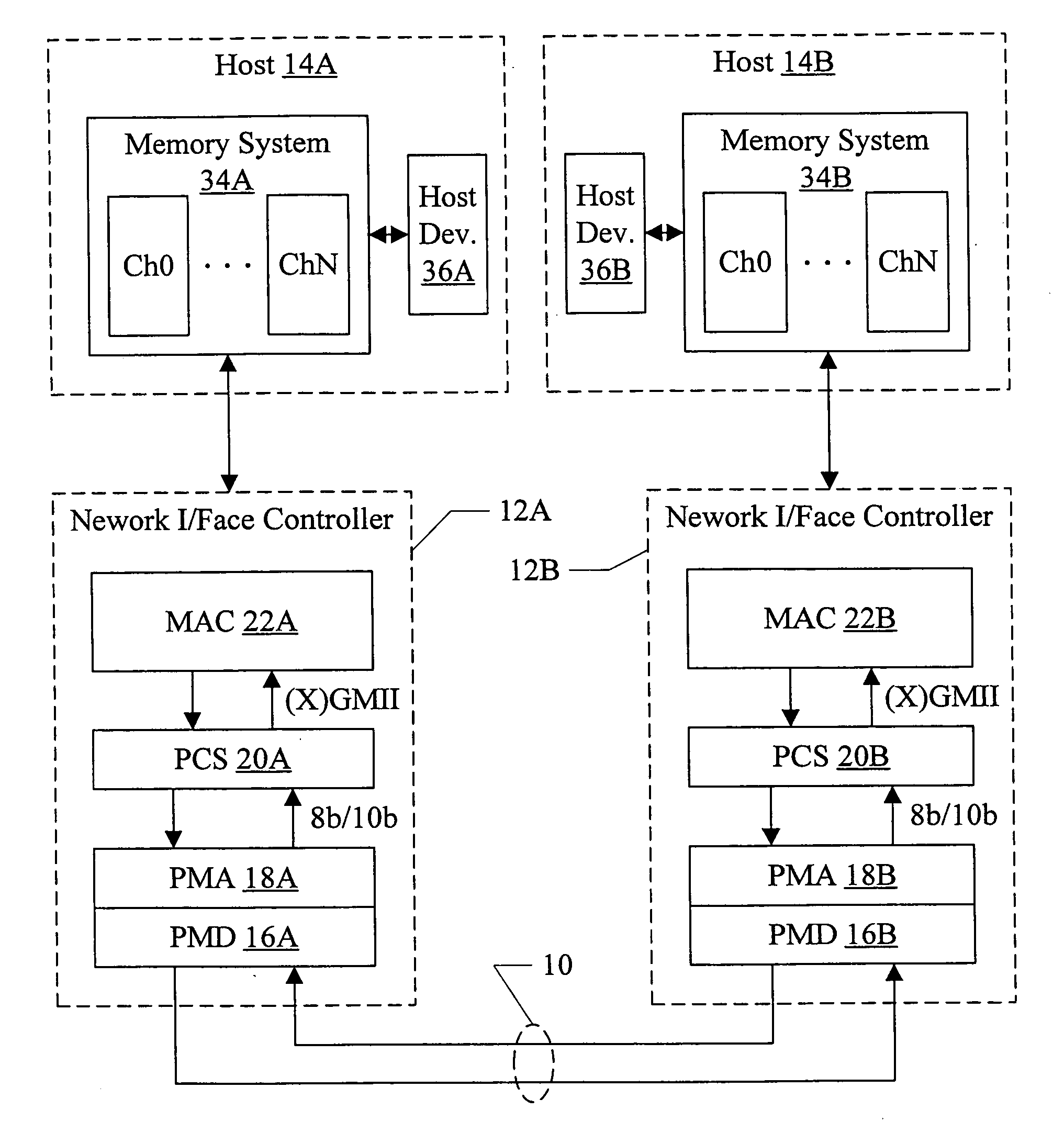
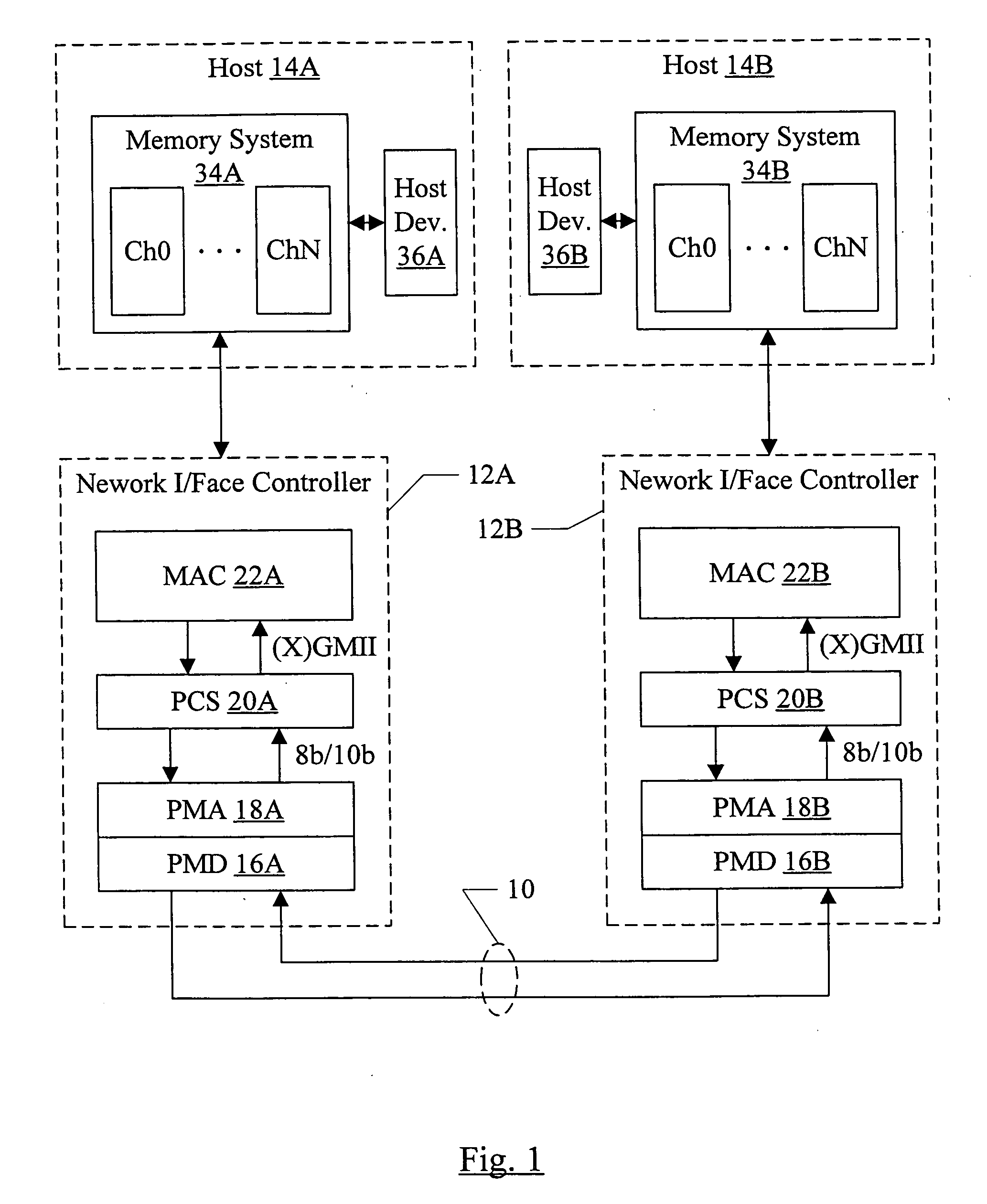
[0029] Turning now to FIG. 1, one embodiment of a networked system is shown. In the illustrated embodiment, the system includes a communication medium 10 over which network communications may be transmitted, network interface controllers 12A-12B coupled to the communication medium 10, and hosts 14A-14B coupled to the network interface controllers 12A-12B, respectively. In the illustrated embodiment, the network interface controller 12A includes a physical media dependent (PMD) layer 16A, a physical media attach (PMA) layer 18A, a physical coding sublayer (PCS) circuit 20A, and a media access controller (MAC) 22A. The PMD 16A is coupled to the communication medium 10 and to the PMA 18A, which is further coupled to the PCS 20A. The PCS 20A is coupled to the MAC 22A. The network interface controller 12B similarly includes a MAC 22B, PCS 20B, PMA 18B, and PMD 16B. The host 14A includes a memory system 34A and may also include other host devices such as host device 36A coupled to the mem...


PUM


Abstract

In one embodiment, a system comprises a communication medium; a first controller coupled to the communication medium; and a second controller coupled to the communication medium. The first controller is configured to interrupt transmission of a packet on the communication medium to the second controller subsequent to transmission of a first portion of the packet. The first controller is configured to transmit at least one control symbol on the communication medium in response to interrupting transmission of the packet, and wherein the first controller is configured to continue transmission of the packet with a second portion of the packet. The controller(s) may include, in some embodiments, a media access controller and a physical coding sublayer.

Description

BACKGROUND [0001] 1. Field of the Invention [0002] This invention is related to the field of network communication and especially Ethernet communication, and more particularly to flow control on networks. [0003] 2. Description of the Related Art [0004] Networking of computers and other electronic devices has become ubiquitous. While a variety of networking standards exist, Ethernet is one of the most popular. In particular, Gigabit Ethernet and 10 Gigabit Ethernet is becoming widely used. [0005] The Ethernet standard currently does not permit the interruption of transmission of a packet. That is, once the first byte of a packet is transmitted on the communication media, the transmission must continue with consecutive bytes to the last byte of the packet without any “bubbles” or wait states in the transmission on the communication media (e.g. twisted pair copper wiring, optical fiber, etc.). If the source of the packet cannot supply all of the bytes of a packet, the packet is termina...

Claims


Application Information

Patent Timeline
IPC IPC(8): H04L12/66H04J3/16
CPCH04L47/10H04L47/245H04L47/13
Inventor DESAI, SHAILENDRA S.HAYTER, MARK D.
Owner APPLE INC
Why Eureka
Try Eureka