
Synchronous control apparatus for initial synchronization when receiving a wireless signal

Inactive Publication Date: 2007-03-01
LAPIS SEMICON CO LTD
View PDF4 Cites 6 Cited by
  • Summary
  • Abstract
  • Description
  • Claims
  • Application Information

AI Technical Summary

Benefits of technology

[0007] It is an object of present invention to provide a synchronous control apparatus for controlling receiving operation in wireless packet communication with synchronization controlled to detect codes to thereby decrease detection errors and attain accurate signal reception.
[0010] DSSS wireless packet communication may thus use a multipath signal and effectively perform an initial synchronization process on a preamble signal, as well as attain a smaller circuit and an improved receiving SNR in its rake receiver. Even when the automatic gain control (AFC) is not in operation as in the initial signal detection or phases vary due to a local signal during transmitting and receiving or a multipath reflection environment, searching for a signal for each multipath may accomplish DSSS wireless packet communication which is insensitive to signal variations not exceeding a predetermined level.
[0011] The initial synchronization process using a preamble signal may accomplish smaller correlator and an improved signal-to-noise ratio. A synchronous control apparatus for reception control in wireless packet communication is thus provided which may control synchronization to detect a code with less detection errors to provide excellent signal receipt.

Problems solved by technology

DSSS communication may also use a particularly short pseudo noise (PN) code length such as the barker code in IEEE (Institute of Electrical and Electronics Engineers) 802.11b specifications, which may cause detection errors more frequently due to noises or the like.

Method used


Image

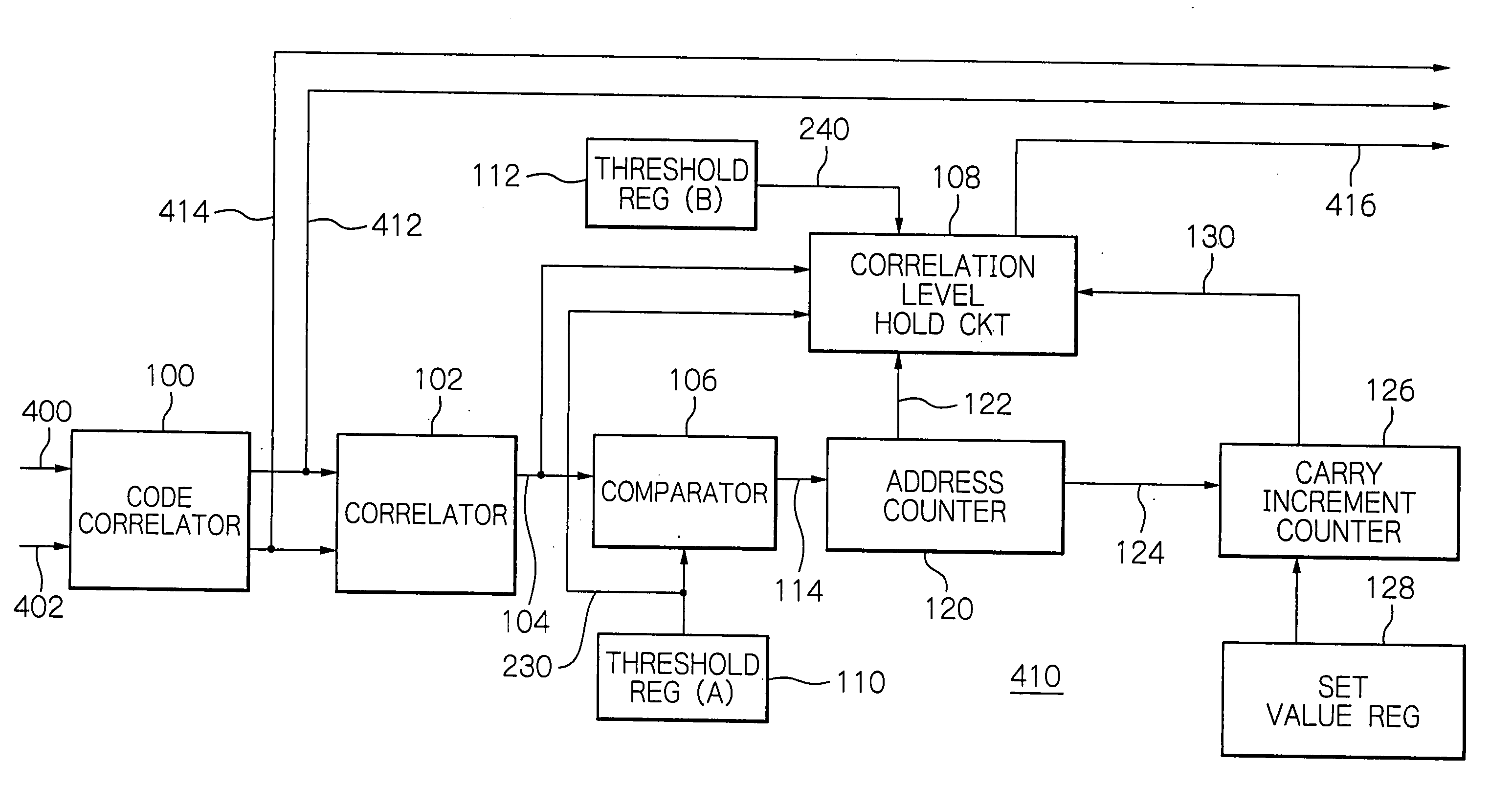
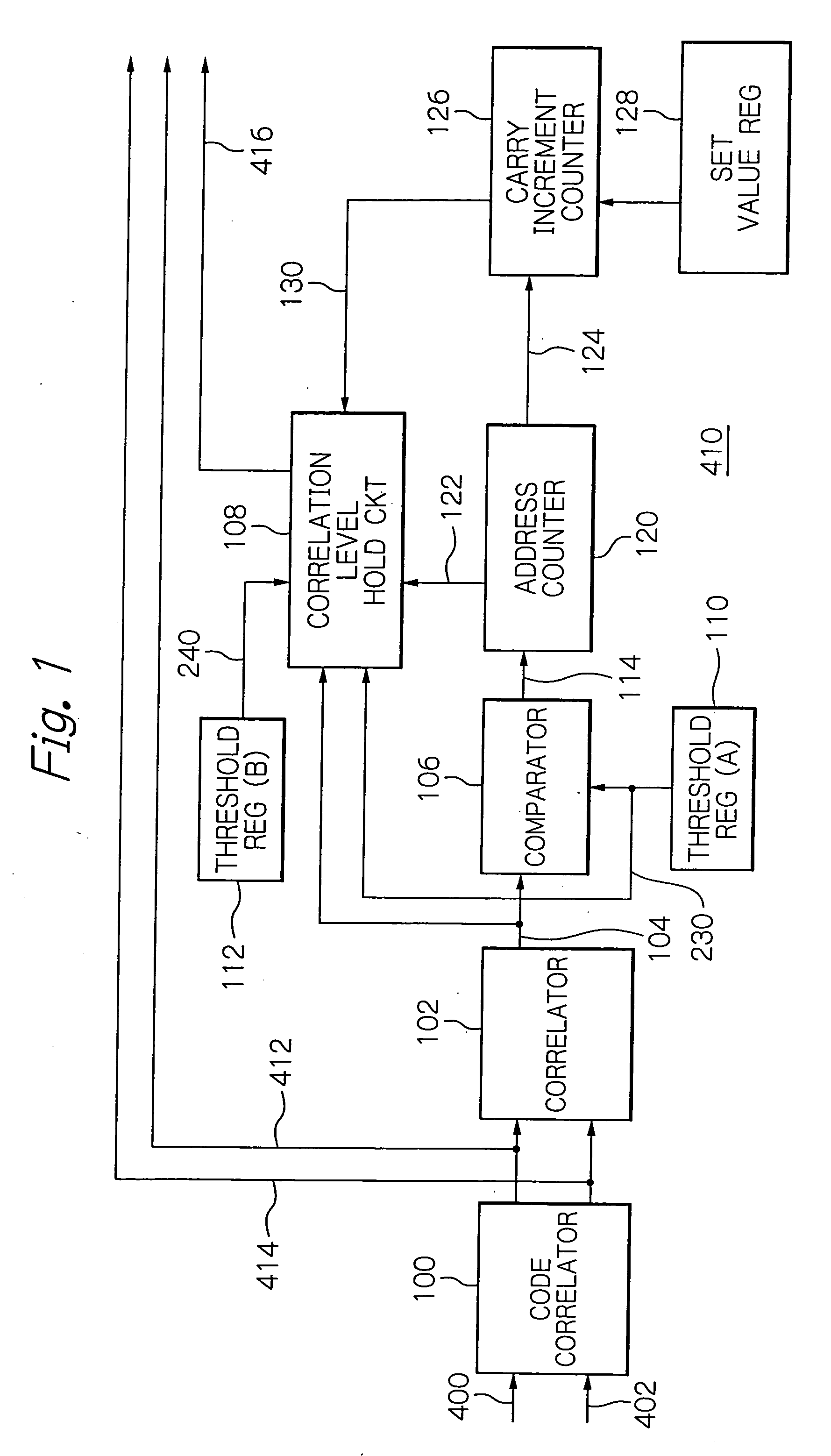
  • Synchronous control apparatus for initial synchronization when receiving a wireless signal
  • Synchronous control apparatus for initial synchronization when receiving a wireless signal
  • Synchronous control apparatus for initial synchronization when receiving a wireless signal

Examples


Embodiment Construction

[0023] Referring now to the accompanying drawings, an embodiment of a synchronous control apparatus according to the present invention will be described in detail. With reference to FIG. 4 first, a preferred embodiment of a receiver will be described which uses a synchronous control apparatus according to the present invention.

[0024] A receiver 10 receives and demodulates a wireless signal transmitted in the direct sequence spread spectrum (DSSS) scheme. As shown, the receiver 10 includes an initial synchronizer 410 for synchronous control and a rake receiver 420 interconnected as illustrated. The synchronous control portion 410 is connected to receive an in-phase signal 400 and a quadrature signal 402 outputted from a demodulator not-shown to detect a code correlation therebetween to thereby detect an initial signal such as a preamble signal to perform an initial synchronization process. The initial synchronizer 410 outputs the code correlations on its outputs 412 and 414. The ini...


PUM


Abstract

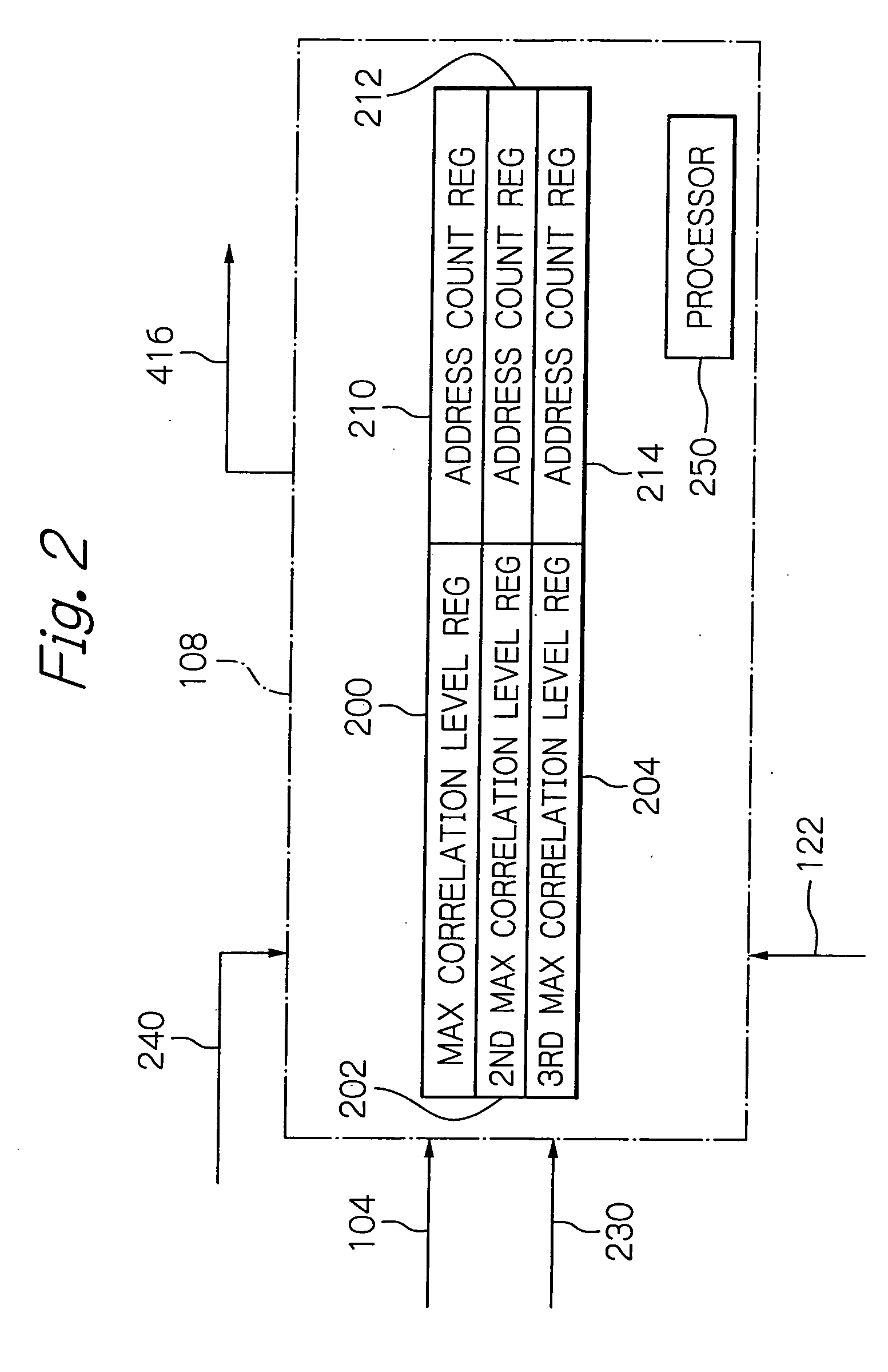
A synchronous control apparatus for reception control in wireless packet communication suppresses detection errors during controlling synchronization to detect codes for improved signal reception. An initial synchronizer includes a code correlator for receiving delayed waves on plural paths. The code correlator outputs a correlation level value through another correlator. The correlation level value is compared with a threshold value from a threshold value register, with the result inputted into an address counter. The correlation level value is also inputted into a correlation level hold circuit. The hold circuit sums the correlation level values obtained in the correlator for a portion of the paths corresponding to a count in the address counter. The hold circuit compares the summed correlation level values with another threshold value from another threshold value register, and uses the result as a basis to set a top timing for receiving delayed waves.

Description

BACKGROUND OF THE INVENTION [0001] 1. Field of the Invention [0002] The present invention relates to a synchronous control apparatus for use in a receiver that receives a wireless signal transmitted in a direct sequence spread spectrum (DSSS) scheme, with accurate initial synchronization established during receiving a wireless signal. [0003] 2. Description of the Background Art [0004] Conventionally, for example, Japanese application patent laid-open publication No. 56218 / 1996 discloses a frame synchronization scheme that reduces, even under a multipath fading environment, a frame timing offset caused by delayed waves to decrease a displacement in frame synchronous position. Japanese application patent laid-open publication No. 178368 / 1998 discloses a rake combining circuit that receives a plurality of delayed incoming waves, performs an inverse spread spectrum demodulation on the received signals, and combines them with the delay adjusted. U.S. Patent Application Publication No. 20...

Claims


Application Information

Patent Timeline
IPC IPC(8): H04B1/00H04L27/06H04B1/707H04B1/7073H04B1/7085H04L7/00H04W16/28H04W56/00
CPCH04B1/7093H04B1/7077
Inventor YAMAUCHI, SHIGEKI
Owner LAPIS SEMICON CO LTD
Learn More