Motion vector estimation apparatus and motion vector estimation method

a technology of motion vector and estimation apparatus, which is applied in the field of motion vector estimation apparatus and motion vector estimation method, can solve the problems of increasing coding has a heavy processing load for the calculation, and the amount of coding is required, so as to reduce the amount of coding, and increase the bit rate

Active Publication Date: 2007-03-01
PANASONIC CORP
View PDF13 Cites 41 Cited by
  • Summary
  • Abstract
  • Description
  • Claims
  • Application Information

AI Technical Summary

Benefits of technology

[0011] So the present invention has been conceived in view of the above problems, and has an object to provide a motion vector estimation apparatus and a motion vector estimation method for red

Problems solved by technology

Furthermore, if the block size of 8×8 pixels is selected, motion vectors are further estimated for four types of sub-macroblocks, and prediction errors are calculated for these sub-macroblocks.
However, in H.264/MPEG-4 AVC, as described above, since motion vectors are estimated for blocks of different sizes (four candidates as macroblock sizes and four candidates as sub-macroblock sizes) and the o

Method used


Image

  • Motion vector estimation apparatus and motion vector estimation method
  • Motion vector estimation apparatus and motion vector estimation method
  • Motion vector estimation apparatus and motion vector estimation method

Examples


first embodiment

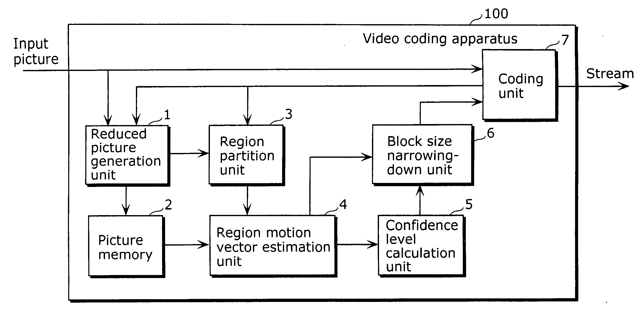
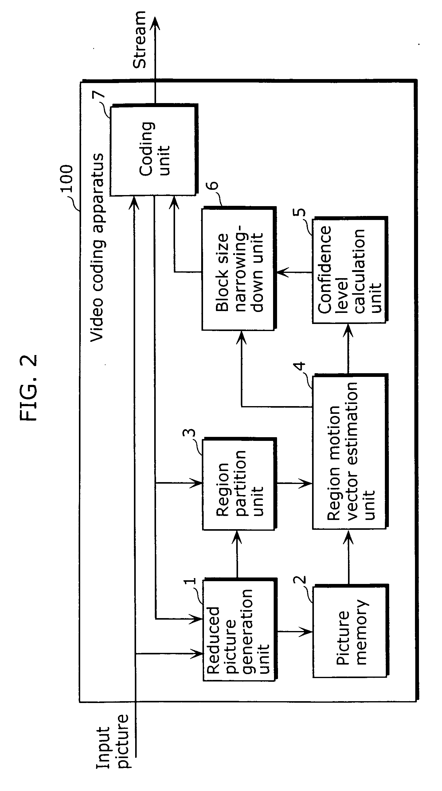
[0033]FIG. 2 is a block diagram showing a structure of a video coding apparatus including a motion vector estimation apparatus according to the first embodiment of the present invention.

[0034] A video coding apparatus 100 is an apparatus for coding an input video sequence on a block-by-block basis, and includes, as shown in FIG. 2, a reduced picture generation unit 1, a picture memory 2, a region partition unit 3, a region motion vector estimation unit 4, a confidence level calculation unit 5, a block size narrowing-down unit 6 and a coding unit 7.

[0035] The reduced picture generation unit 1 receives a current picture to be coded including a current block to be coded, as well as a reference picture which is referred to for estimation of a motion vector used for coding the current block, performs calculation for reducing the number of pixels of the current picture to generate a reduced current picture to be coded, and performs calculation for reducing the number of pixels of the re...

second embodiment

[0063]FIG. 9 is a block diagram showing a structure of a video coding apparatus including a motion vector estimation apparatus according to the second embodiment of the present invention. Note that the same reference numbers are assigned to the same constituent elements as those of the video coding apparatus 100 in the first embodiment as described with reference to FIG. 2. Therefore, a detailed description of these constituent elements is not repeated here.

[0064] A video coding apparatus 300 includes a block size determination unit 301 and a picture memory 302 as shown in FIG. 9, in addition to the constituent elements of the video coding apparatus 100.

[0065] In the case where as a result of the judgment of the block size narrowing-down unit 6 whether or not each region motion vector is greater than the predetermined threshold value and the confidence level of the region motion vector is higher than the predetermined threshold value, no region motion vector satisfy these conditio...


PUM


Abstract

A motion vector estimation apparatus that can reduce an amount of calculation for video coding processing and thus achieve a higher bit rate and lower consumption power, while contributing to improvement in image quality and coding efficiency include: a reduced picture generation unit which generates a reduced current picture to be coded and a reduced reference picture; a region partition unit which partitions a reduced current picture to be coded into regions and generates reduced region images; a region motion vector estimation unit which estimates a region motion vector of a reduced region image; a confidence level calculation unit which calculates a confidence level of a region motion vector; and a block size narrowing-down unit which narrows down candidate block sizes so as to determine a block size to be used for coding a current block to be coded, based on a region motion vector and a confidence level of the region motion vector.

Description

BACKGROUND OF THE INVENTION [0001] (1) Field of the Invention [0002] The present invention relates to a motion vector estimation apparatus for estimating a motion vector of a current block to be coded in a current picture to be coded. [0003] (2) Description of the Related Art [0004] With the advances in semiconductor technology and the like, various coding schemes for video compression have been introduced to home video recorders. In particular, coding schemes such as MPEG-2, MPEG-4 and the like which exploit motion vectors between a number of pictures constituting a video sequence have been widely used. [0005] A motion vector estimation apparatus using such a coding scheme estimates a motion vector between pictures on a block-by-block basis. Particularly, H.264 / MPEG-4 AVC gives the encoder the ability to choose which block size, from among a number of block sizes, will be used for the most efficient coding (see, for example, Yoichi Yagasaki, et al., “Jisedai Dogazo Fugoka Hoshiki M...

Claims


Application Information

Patent Timeline
IPC IPC(8): H04N11/02H04N11/04H04N19/50H03M7/36H04N5/92H04N19/119H04N19/127H04N19/132H04N19/134H04N19/137H04N19/139H04N19/196H04N19/503H04N19/51H04N19/543H04N19/59H04N19/593H04N19/60H04N19/61H04N19/91
CPCH04N19/61H04N19/132H04N19/156H04N19/521H04N19/53H04N19/543H04N19/182
Inventor MARUYAMA, YUUKIJURI, TATSUROARAKAWA, HIROSHISAIGO, KATSUOARIMURA, KOJIOHGOSE, HIDEYUKITASAKA, KEI
Owner PANASONIC CORP
Why Eureka
Try Eureka