Trans-retinal flexible circuit electrode array

a flexible circuit and electrode array technology, applied in the field of neuronal stimulation, can solve problems such as cutting delicate retina tissue, and achieve the effect of cutting delicate retina tissu

Inactive Publication Date: 2007-03-01
SECOND SIGHT MEDICAL PRODS +1
View PDF23 Cites 15 Cited by
  • Summary
  • Abstract
  • Description
  • Claims
  • Application Information

AI Technical Summary

Benefits of technology

[0017] The present invention is an improved electrode array for subretinal stimulation. A hard polymer such as polyimide is biocompatible and strong for supporting an electrode array and supporting traces in a thin flex circuit array. The applicants describe the disadvantage of material such as polyimide is that when made thin, it can cut delicate retina tissue. Th...

Problems solved by technology

The applicants describe the disadvantage of material such as ...

Method used


Image

  • Trans-retinal flexible circuit electrode array
  • Trans-retinal flexible circuit electrode array
  • Trans-retinal flexible circuit electrode array

Examples


Embodiment Construction

[0029] The following description is of the best mode presently contemplated for carrying out the invention. This description is not to be taken in a limiting sense, but is made merely for the purpose of describing the general principles of the invention. The scope of the invention should be determined with reference to the claims.

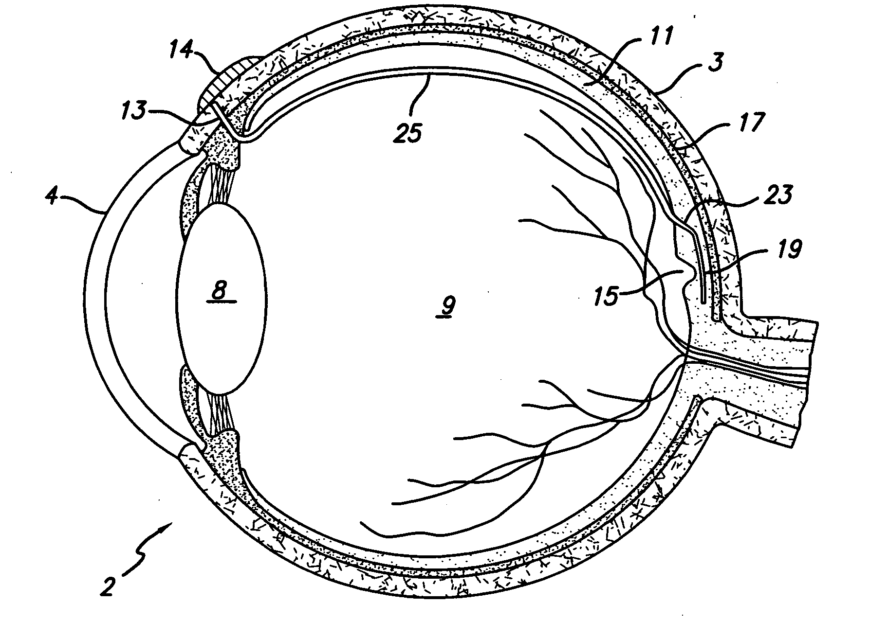
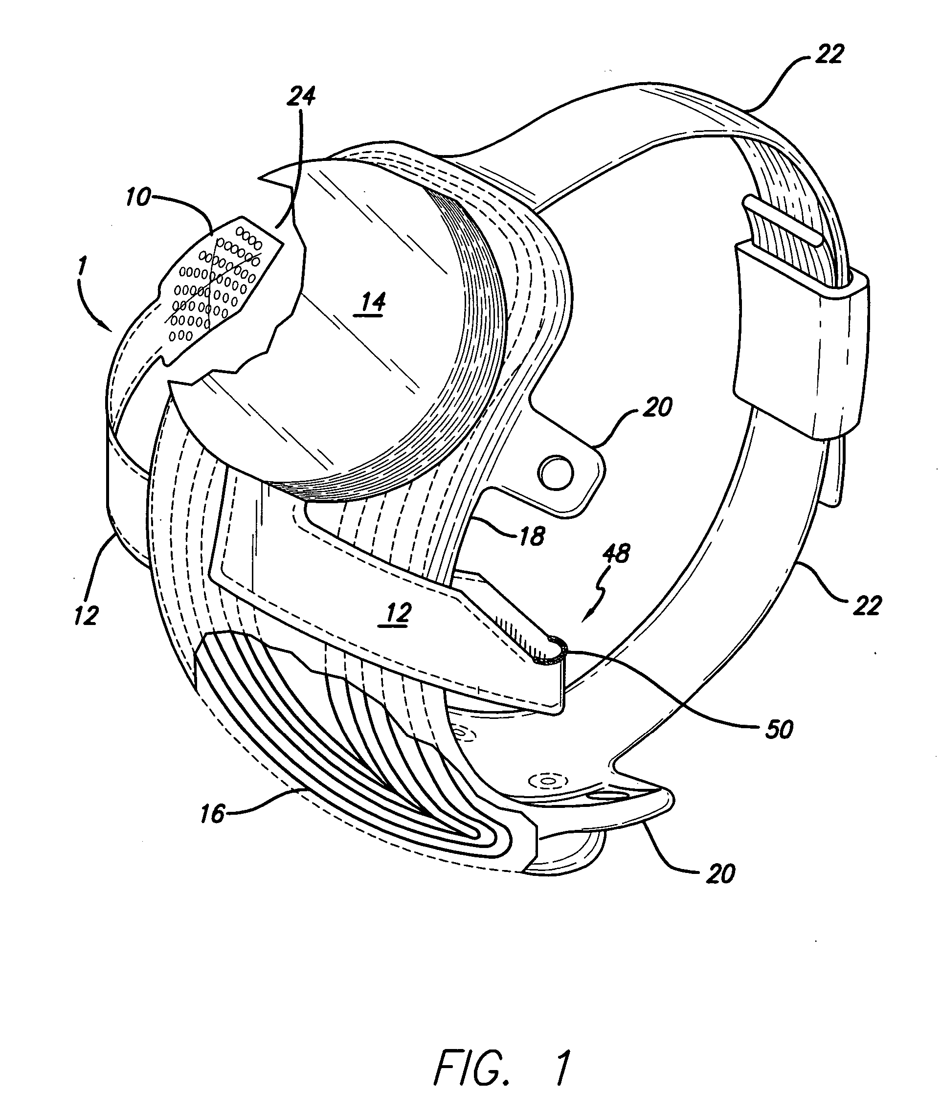
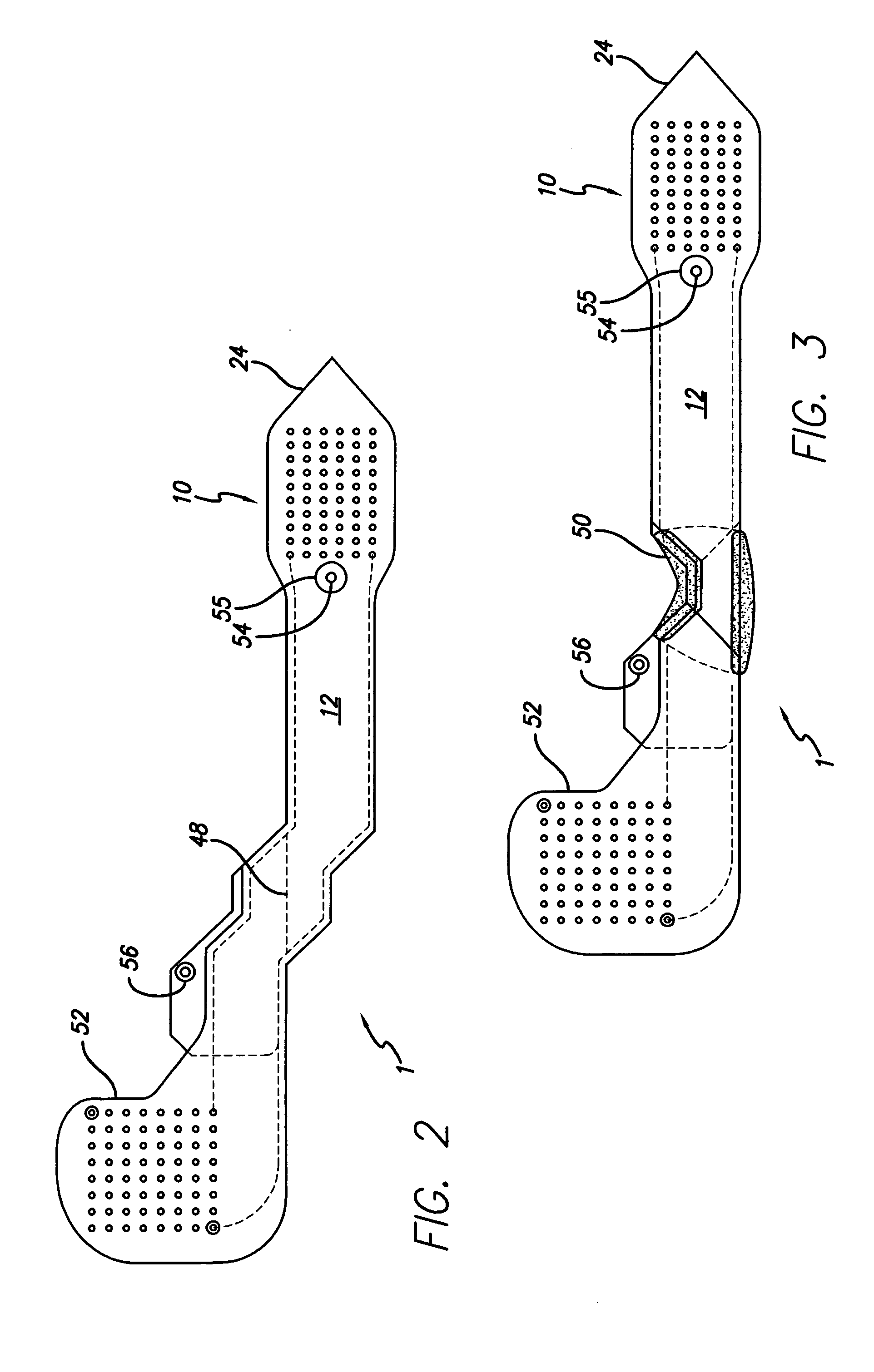
[0030]FIG. 1 shows a perspective view of the implanted portion of the preferred retinal prosthesis. A flexible circuit 1 includes a flexible circuit electrode array 10. The flexible circuit electrode array 10 is electrically coupled by a flexible circuit cable 12, which pierces first the sclera, then the retina and is electrically coupled to an electronics package 14, external to the sclera. The flexible circuit 1 further forms a point 24 at its end, beyond the flexible circuit electrode array 10. While the point 24 aids in passing the flexible circuit 1 through the sclerotomy, it is particularly useful for passing the flexible circuit 1 through the retina...


PUM


Abstract

Applicant has proposed a combination of the subretinal and epiretinal methods by placing the electronics external to the eye, entering the eye through the pars plana and the piercing the retina (retinotomy) from inside the eye to stimulate subreintally. The present invention is an improved electrode array for subretinal stimulation. A hard polymer such as polyimide is biocompatible and strong for supporting an electrode array and supporting traces in a thin flex circuit array. In the present invention applicant takes advantage of the sharp nature of thin polyimide making a point on the end of the electrode array. This allows the flexible circuit electrode array to be both electrode array and surgical tool to cut the retinal and slide the array under the retina in a single action.

Description

CROSS-REFERENCE TO RELATED APPLICATIONS [0001] This claims the benefit of U.S. Provisional Application No. 60 / 718,779, “Transretinal Flexible Circuit Electrode Array”, filed Sep. 19, 2005, the disclosures of all are incorporated herein by reference. [0002] This application is a Continuation-In-Part of U.S. application Ser. No. 10 / 393,887, “Transretinal Implant and Method of Manufacture”, filed Mar. 21, 2003, the disclosure of which is incorporated herein by reference. [0003] This application is a Continuation-In-Part of U.S. application Ser. No. 11 / 413,689, “Flexible circuit electrode array”, filed Apr. 28, 2006, which is a Continuation-In-Part of U.S. application Ser. No. 11 / 207,644, “Flexible circuit electrode array”, filed Aug. 19, 2005 which claims the benefit of U.S. Provisional Application No. 60 / 676,008, “Thin Film Electrode Array”, filed Apr. 28, 2005, the disclosures of all are incorporated herein by reference.GOVERNMENT RIGHTS NOTICE [0004] This invention was made with gov...

Claims


Application Information

Patent Timeline
IPC IPC(8): A61N1/36
CPCA61F9/08A61N1/0543A61N1/36046H05K2201/0133H05K1/0281H05K1/118H05K3/28H05K1/028
Inventor GREENBERG, ROBERT J.HUMAYUN, MARK S.
Owner SECOND SIGHT MEDICAL PRODS
Why Eureka
Try Eureka