
Craft Punch with Replaceable Cutting Tool

a cutting tool and punch technology, applied in the field of handicrafts, to achieve the effect of convenient replacement of the lower cutting tool, simple structure, and scientific

Active Publication Date: 2014-11-20
ZHANG YINGYUAN
View PDF18 Cites 1 Cited by
  • Summary
  • Abstract
  • Description
  • Claims
  • Application Information

AI Technical Summary

Benefits of technology

The present invention provides a craft punch that is easy to use, saves resources, and improves operating efficiency. It allows for easy replacement of the lower and upper cutting molds. The lower part of the main body has a receiving groove and a positioning groove, with a locking member that is used to position the lower cutting mold holder. The locking member has a convex positioning column for rapid locking of a straight line positioning member and an angle positioning member. The craft punch is simple in construction, flexible in use, and conforms to industrial applications, improving production efficiency. Overall, it provides a high-quality, cost-effective solution for craft punch needs.

Problems solved by technology

Under such a mode of production, a lot of raw materials need to be used to produce a lower cutting mold holder part which is relatively hard enough to bear the force of impact from the upper cutting mold, and a single upper cutting mold holder and a single lower cutting mold holder need to be produced for cutting each shape, so that it is a resource-wasting production method; in addition, as the upper cutting mold needs to extend from the upper part of the lower cutting mold holder to the bottom, the upper cutting mold with enough length needs to be produced, and it is also a kind of waste of resources; in addition, the craft punch product with each single shape could be formed by plastic caps, parts, springs and multiple procedures, which also causes another kind of waste; finally, the traditional craft punch produced in this way is inflexible, and only could be used for cutting on a piece of paper in one direction.

Method used


Image

  • Craft Punch with Replaceable Cutting Tool
  • Craft Punch with Replaceable Cutting Tool
  • Craft Punch with Replaceable Cutting Tool

Examples


Embodiment Construction

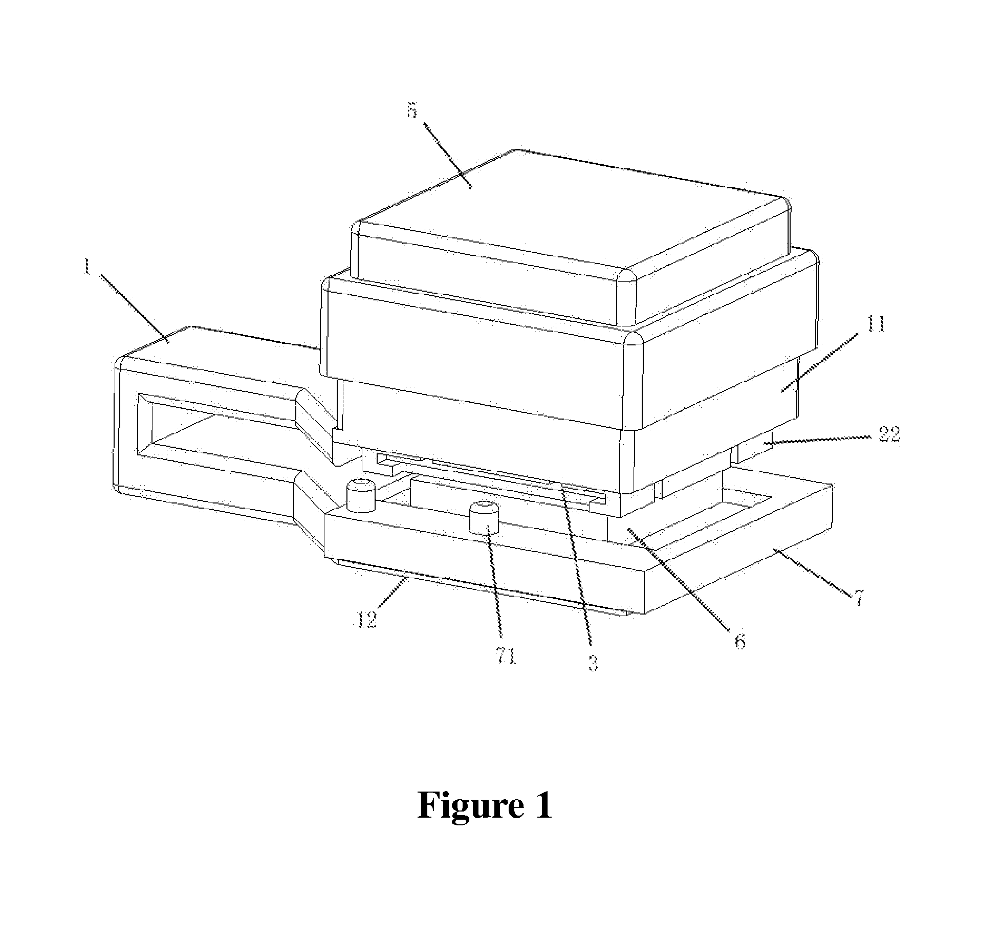
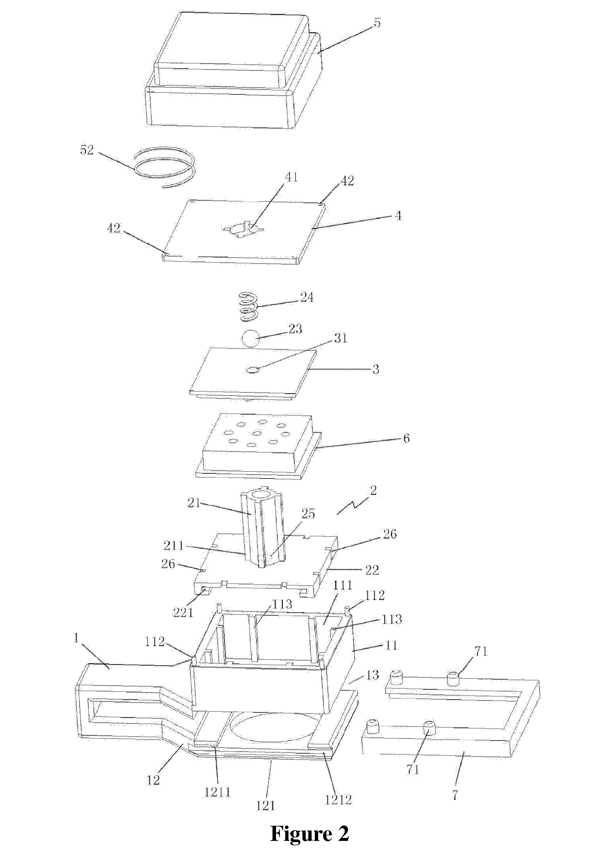
[0020]The present invention could be further illustrated via the following accompanying drawings:

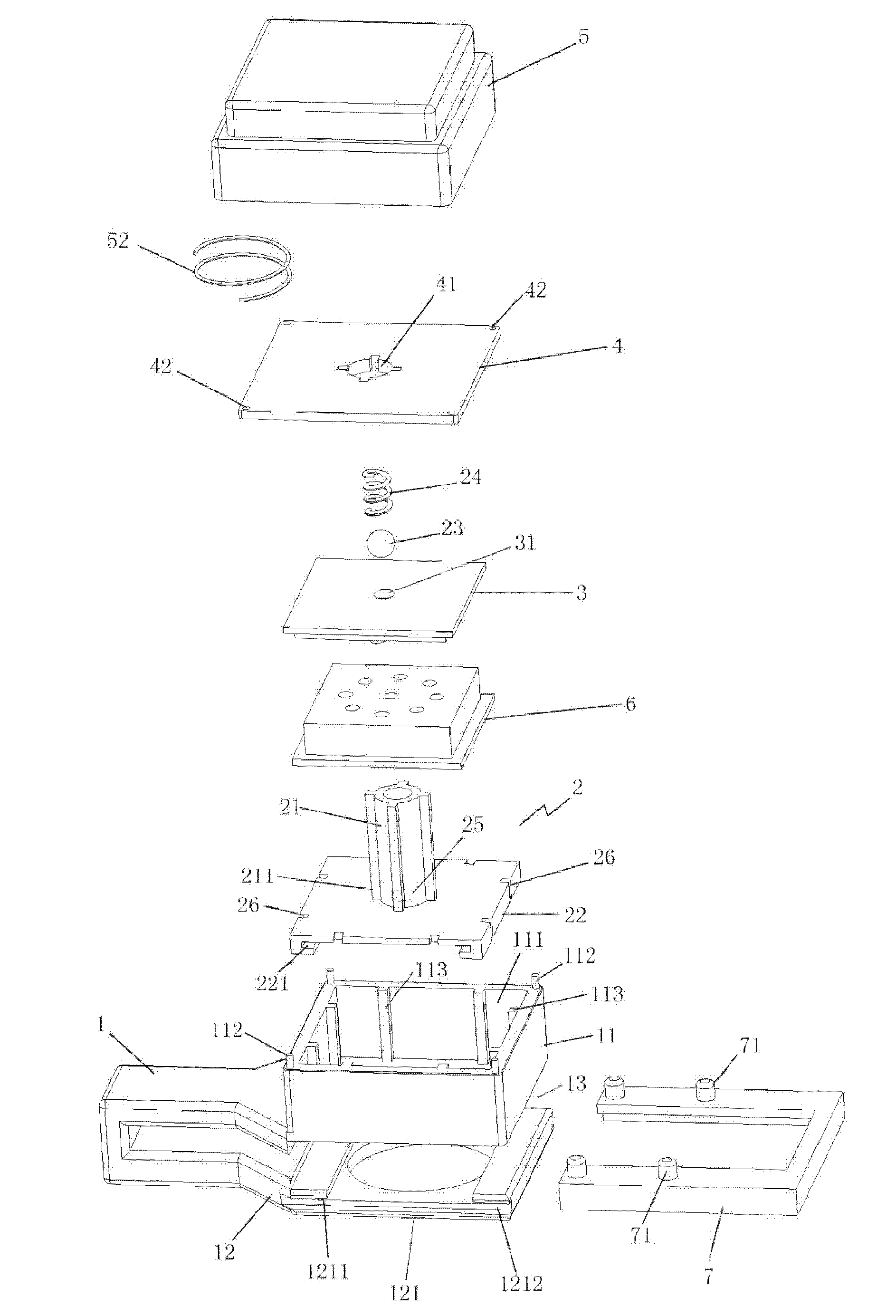
[0021]FIGS. 1, 2, 3 and 4 are schematic diagrams of better embodiments of the present invention. The present invention relates to a craft punch with a replaceable cutting tool, comprising a main body 1, wherein the main body 1 has an upper part 11 and a lower part 12 which are spaced up and down, a gap 13 allowing paper to be inserted is formed between the upper part 11 and the lower part 12, the upper part 11 has a passage 111, and the lower part 12 has a receiving part 121 to movably receive a lower cutting mold holder 6; an upper cutting mold holder receiving component 2, which could be installed in the passage 111 on the upper part 11 of the main body movably up and down, wherein the upper side of the upper cutting mold holder receiving component 2 bulges to form a tubular part 21, and one side of the upper cutting mold holder receiving component back to the tubular part is provided ...


PUM


Abstract

A craft punch with a replaceable cutting tool includes a main body having an upper part and a lower part which are spaced up and down. The upper part has a passage, and the lower part has a receiving part to movably receive a lower cutting mold holder. An upper cutting mold holder receiving component could be installed in the passage movably up and down, the upper side of the receiving component bulges to form a tubular part, and one side of the receiving component back to the tubular part is provided with a receiving part which could movably receive an upper cutting mold; a cover plate covers the upper end of the passage and is provided with a through hole allowing the tubular part to pass through an upper bulge, and an upper cover covers the upper side of the cover plate, and is connected with the tubular part.

Description

TECHNICAL FIELD[0001]The present invention relates to the technical field of handicrafts, and in particular relates to a tool for the production of handicrafts.BACKGROUND[0002]Craft punch is a tool for the production of handicrafts, which is widely used at present. A traditional craft punch consists of two major parts which are part 1, a lower cutting mold: its production process is as follows: a complete lower cutting mold holder with (negative) cutting shape is produced, wherein the cutting shape penetrates through from the top till the bottom in a hollow form, and then a part on the lower cutting mold holder is horizontally sawn to form a gap. As it is not sawn off completely, the lower cutting mold is still integrated, only the part in the (negative) cutting shape on the lower cutting mold holder is divided into upper and lower parts, and the gap is to allow paper to be inserted; and part 2 is an upper cutting mold which is mainly used for cutting and has a cutting shape the sam...

Claims


Application Information

Patent Timeline
IPC IPC(8): B26F1/14B26F1/32
CPCB26F1/32B26F1/14B26F1/36B26D2007/2607B26F1/02
Inventor HUANG, LIJUAN
Owner ZHANG YINGYUAN
Learn More