Bypass valve for internal combustion engines

a bypass valve and internal combustion engine technology, applied in the direction of closures, exhaust gas recirculation, non-fuel substance addition to fuel, etc., can solve the problems of over-excited electromagnetic actuator size and excessive opening time of bypass valves of this type, and achieve low pneumatic pressure, prevent short surging of turbocharger, and high flow rate

Inactive Publication Date: 2007-03-08
PIERBURG GMBH & CO KG NEUSS
View PDF12 Cites 12 Cited by
  • Summary
  • Abstract
  • Description
  • Claims
  • Application Information

AI Technical Summary

Benefits of technology

[0007] This object is achieved in that the pressure equalization openings are arranged or embodied in such a way that during the opening of the bypass valve, a pressure that is reduced in comparison with the pressure prevailing in the closed state can be introduced into the at least one chamber. Through such an arrangement and embodiment of the pressure equalization openings, it is possible to obtain a valve that is approximately pressure-balanced even during the opening and closing. During the opening, a high flow rate and thus a low pneumatic pressure arises in the gap between t

Problems solved by technology

In spite of the arrangement of these pressure equalization openings, however, the opening times of a bypass valve of this type continue t

Method used


Image

  • Bypass valve for internal combustion engines
  • Bypass valve for internal combustion engines
  • Bypass valve for internal combustion engines

Examples


Embodiment Construction

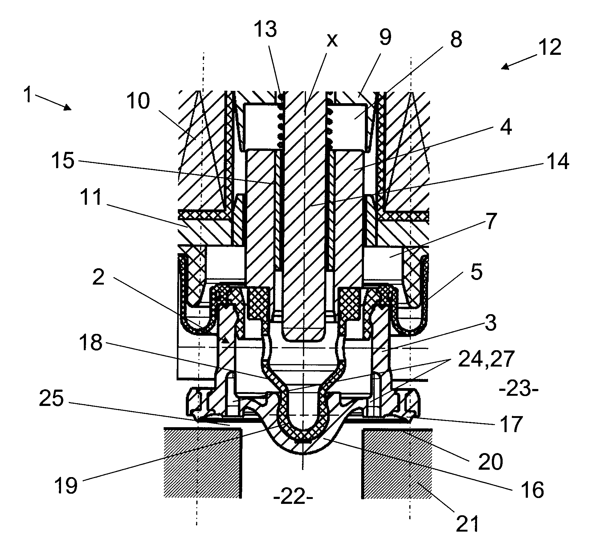
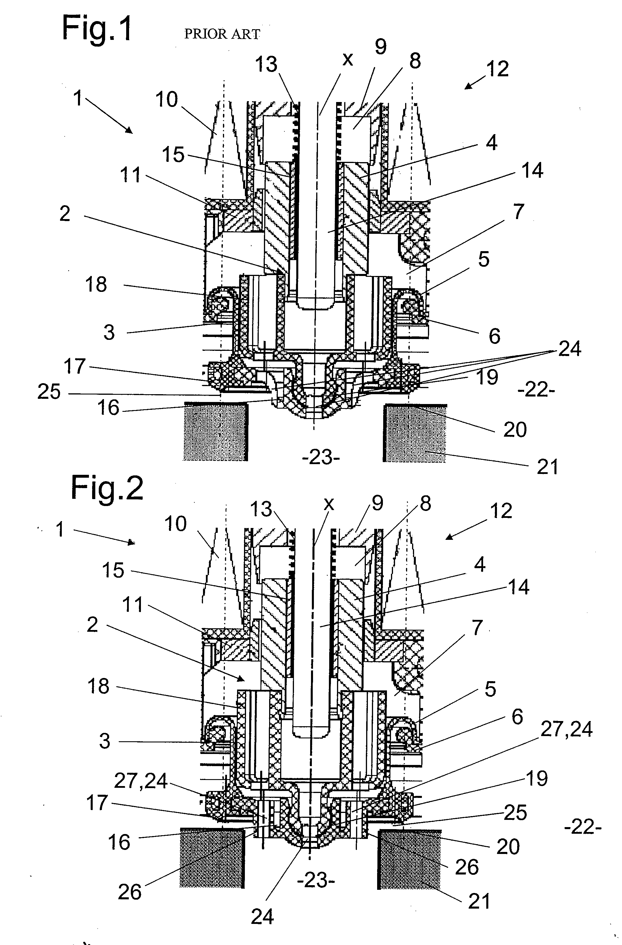
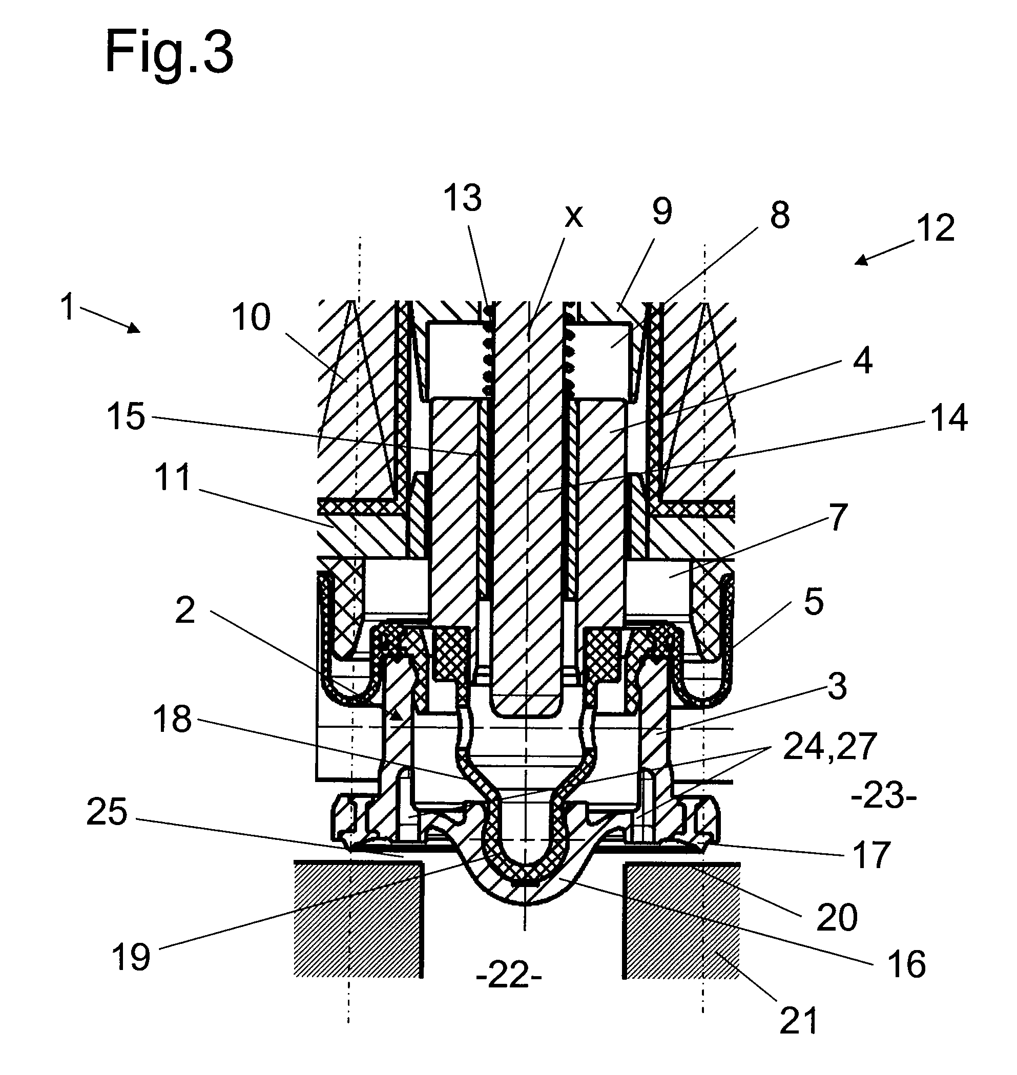
[0017] The bypass valve 1 shown in FIG. 1 serves as a divert air valve according to the known prior art. It comprises a movable valve unit 2 that is composed essentially of a valve closing body 3 and a movable armature 4 that is connected to the valve closing body 3. Around the valve closing body 3 a membrane 5 is arranged that with its radial outer circumference is fixed to a housing 6 of the bypass valve 1 and whose inner radial circumference is connected to the valve closing body 3, so that a chamber 7 is embodied inside the housing 6. This chamber 7 is in fluid connection with a chamber 8 that is formed between a core 9 of the bypass valve 1 and the armature 4. A coil 10 is arranged around the core 9 for activating the bypass valve 1. The coil 10 as well as the core 9 of the movable armature 4 as well as a back closure plate 11 form a magnetic circuit of an actuator 12 integrated into the bypass valve 1.

[0018] A coil spring 13 that is arranged around a valve rod 14 is supported...


PUM


Abstract

The invention describes a bypass valve (1) that can be used as a divert air valve. Bypass valves (1) that work in the closed or opened position in a force-balanced or pressure-balanced manner are known. During the opening of the bypass valve (1), a lower pressure is produced in a gap (25) between a valve closing body (3) and a valve seat (20), which pressure destroys the force balance and thus loads a movable valve unit (2) in the closing direction. In order to prevent this, according to the invention pressure equalization openings (24) are embodied or arranged with respect to the gap (25) in such a way that a reduced pressure is introduced into the chambers (7, 8) in the interior of the valve, so that the closing-operative force is distinctly reduced. By these means, the opening times of such a bypass valve can be distinctly reduced.

Description

[0001] This application claims priority from German Patent Application No. 10 2005 042 679.4, filed Sep. 8, 2005, the entire disclosure of which is incorporated herein by reference. FIELD OF THE INVENTION [0002] The invention relates to a bypass valve for internal combustion engines that controls a bypass channel and features a valve unit that can be moved translationally via an actuator, which valve unit features a valve closing body that corresponds to a valve seat in such a way that an area of higher pressure can be separated from an area of lower pressure, whereby the movable valve unit features pressure equalization openings via which the area of higher or lower pressure is connected to at least one inner chamber of the bypass valve. BACKGROUND OF THE INVENTION [0003] Such bypass valves, in which an area of higher pressure can be separated from an area of lower pressure by means of a valve and can be connected to the latter, are known for example as divert air valves for intern...

Claims


Application Information

Patent Timeline
IPC IPC(8): F02D23/00
CPCF02B29/0418F02B37/16F02B39/00Y02T10/144Y02T10/121Y02T10/146F02M25/0729F02M26/26Y02T10/12
Inventor THIERY, MICHAELMIEMCZYK, DIETMARKRAUSE, HARALD
Owner PIERBURG GMBH & CO KG NEUSS
Why Eureka
Try Eureka