Turbo set with starting device

a technology of starting device and turbine set, which is applied in the direction of engine starter, turbine/propulsion engine ignition, machine/engine, etc., can solve the problems of high construction cost, no function, and high cost of static frequency converter required for this purpose, and achieve the effect of increasing the steam quantity

Inactive Publication Date: 2007-03-08
ALSTOM TECH LTD
View PDF18 Cites 8 Cited by
  • Summary
  • Abstract
  • Description
  • Claims
  • Application Information

AI Technical Summary

Benefits of technology

[0033] Furthermore, the combustion of hydrogen and oxygen in a hydrogen reaction affords the advantage that the pressure level at which the combustion reaction takes place and therefore also the outlet pressure of the generated steam can easily be regulated. Thus, it is possible in a simple way, and, in particular, without necessitating a compressor, to ensure that the generated steam has a sufficient overpressure to provide a pressure drop sufficient for the steam flow from the steam generator as far as the outlet from the turbo set.
[0034] Expediently, water is supplied additionally to the generated steam before the supply of the latter into the flow path of the turbo set. This supply of water serves, on the one hand, for cooling the generated steam and, on the other hand, for increasing the steam quantity.

Problems solved by technology

However, the static frequency converters required for this purpose are costly and do not perform any function when the plant has warmed up.
The solution of starting a gas turbine plant by means of the injection of compressed air has the disadvantage, however, that a relatively large reservoir has to be made available so that sufficient compressed air can be stored.
Particularly in the case of large stationary gas turbine plants, this can be implemented only via very large accumulator volumes which entail relatively high costs in terms of construction.
If, for example, an operation to start the plant is discontinued at the first attempt, a second starting attempt usually cannot be carried out immediately thereafter.

Method used


Image

  • Turbo set with starting device
  • Turbo set with starting device
  • Turbo set with starting device

Examples


Embodiment Construction

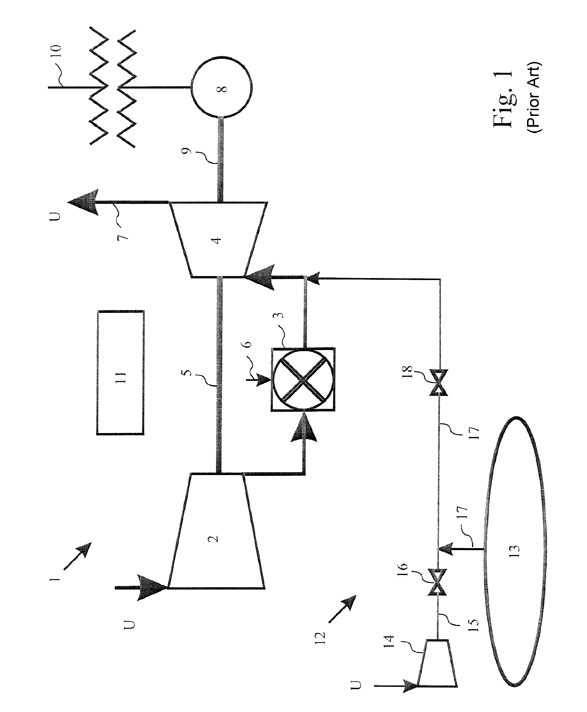
[0041]FIG. 1 shows a diagrammatic illustration of a gas turbine plant 1, such as is familiar to a person skilled in the art. The gas turbine plant 1, designed here as a stationary plant, serves for the generation of current. However, in principle, the invention may also be applied to mobile plants or turbo sets used in another way.

[0042] The gas turbine plant 1 includes a compressor 2 which sucks in air on the entry side from the surroundings U and compresses this. The compressor 2 is drive-connected fixedly in terms of rotation to a turbine 4 by a shaft 5. In the gas path between the compressor 2 and turbine 4 is arranged a combustion chamber 3 which is fed with fuel for firing via the fuel supply line 6. After passing through the turbine 4, the air / fuel-gas mixture flows into the surroundings U again via an exhaust gas line 7. The turbine 4 is drive-connected to a generator 8 via a further shaft 9. The shafts 5 and 9 may also be produced in one piece. During operation, the gas tu...


PUM


Abstract

In a turbo set (100) with a starting device (120), the turbo set includes a compressor (102), a combustion chamber (103), and a turbine (104) which are arranged along a flow path of the turbo set. The starting device (120) serves for starting the turbo set and includes a steam generator (121) for the generation of steam which is under overpressure and a supply line (125) for supplying the steam into the flow path (101) of the turbo set (100). In a method for starting the turbo set, the method includes generating steam which is under overpressure and supplying the steam into the flow path of the turbo set.

Description

[0001] This application claims priority under 35 U.S.C. §119 to Swiss application number 00688 / 05, filed 18 Apr. 2005, the entirety of which is incorporated by reference herein. BACKGROUND OF THE INVENTION [0002] 1. Field of the Invention [0003] The invention relates to a turbo set with a starting device for starting the turbo set. The invention relates, furthermore, to a method for starting the turbo set. [0004] 2. Brief Description of the Related Art [0005] The prior art discloses several methods and devices for starting turbo sets, such as, for example, mobile or stationary gas or steam turbine plants or other turbo sets. Particularly in the case of plants which are operated in a stationary way for current generation, the starting of the turbo set demands very stringent requirements from the starting device and the regulation of the starting operation on account of the high powers of the turbo set along with the often very high rotor inertias. [0006] To start a gas turbine plant,...

Claims


Application Information

Patent Timeline
Patent Type & Authority Applications(United States)
IPC IPC(8): F02C7/26
CPCF01D15/10F01D19/00F01K21/047F05D2210/12F02C7/27Y02E20/16F05D2260/85F02C3/22
Inventor ALTHAUS, ROLF
Owner ALSTOM TECH LTD
Why Eureka
Try Eureka