Valve timing adjusting apparatus

a timing adjustment and valve technology, applied in valve drives, couplings, machines/engines, etc., can solve the problems of noise and damage, wear and seizing between the camshaft, and the crankshaft side rotatable body is likely to be wobbled by the amount, so as to reduce noise and damage, the effect of improving durability

Active Publication Date: 2007-03-08
DENSO CORP
View PDF5 Cites 33 Cited by
  • Summary
  • Abstract
  • Description
  • Claims
  • Application Information

AI Technical Summary

Benefits of technology

[0008] The present invention addresses the above disadvantages. Thus, it is an objective of the present invention to provide a valve timing adjusting apparatus, which achieves an improved durability. It is another objective of the present invention to provide a valve timing adjusting apparatus, which limits generation of noise.

Problems solved by technology

In this case, the crankshaft side rotatable body is locally engaged with the camshaft, so that wearing and seizing between the crankshaft side rotatable body and the camshaft are likely to occur.
Furthermore, in the above supporting structure, when an oscillating torque of the camshaft is transmitted to the differential gear mechanism, the crankshaft side rotatable body is wobbled by the amount that corresponds to the clearance between the crankshaft side rotatable body and the camshaft.
In this case, the crankshaft side rotatable body is wobbled relative to the camshaft, so that noise and a damage could possibly occur.

Method used


Image

  • Valve timing adjusting apparatus
  • Valve timing adjusting apparatus
  • Valve timing adjusting apparatus

Examples


first embodiment

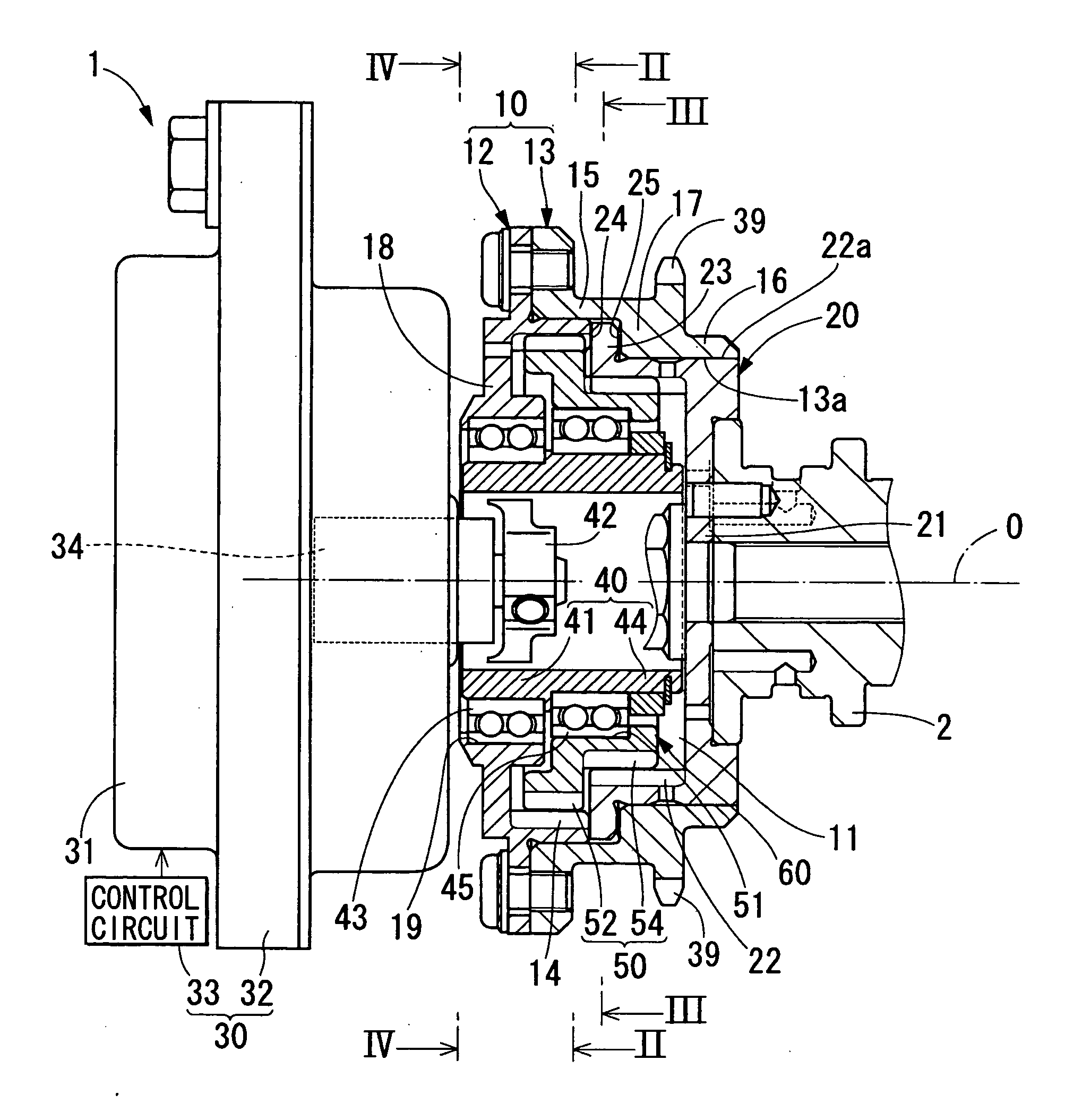
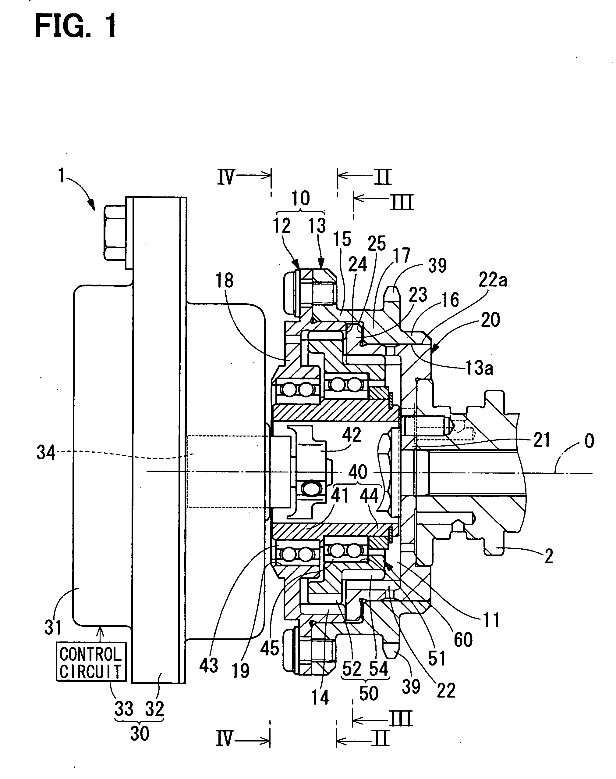
[0017]FIG. 1 shows a valve timing adjusting apparatus 1 according to a first embodiment of the present invention. The valve timing adjusting apparatus 1 is provided in a transmission system, which transmits an engine torque from a crankshaft of an internal combustion engine to a camshaft 2. The valve timing adjusting apparatus 1 changes a relative rotational phase between the crankshaft and the camshaft 2 to adjust valve timing of an intake valve of the internal combustion engine. In FIG. 1, a top-to-bottom direction corresponds to the actual vertical direction, and a left-to-right direction, along which a rotational axis O extends, corresponds to the actual horizontal direction.

[0018] The valve timing adjusting apparatus 1 includes a driving-side rotatable body 10, a driven-side rotatable body 20, a control unit 30, a planet carrier 40 and a planet gear 50.

[0019] The driving-side rotatable body 10 and the driven-side rotatable body 20 cooperate together to form a receiving space ...

second embodiment

[0036] As shown in FIG. 5, a second embodiment of the present invention is a modification of the first embodiment, and therefore components similar to those of the first embodiment will be indicated by the same numerals and will not be described further.

[0037] A sprocket 113 of a driving-side rotatable body 110 of a valve timing adjusting apparatus 100 according to the second embodiment includes first to third cylindrical portions 115-117. The first cylindrical portion 115 and the third cylindrical portion 117 have the substantially the same construction as the large diameter portion 15 and the stepped portion 17, respectively, of the first embodiment. The second cylindrical portion 116 is formed in a cylindrical body, which has a diameter larger than that of the small diameter portion 16. A bearing 120 is interposed between an inner peripheral wall 116a of the second cylindrical portion 116 and the outer peripheral wall 22a of the driven-side inner gear 22.

[0038] The bearing 120 ...


PUM


Abstract

A driving-side rotatable body includes a driving-side inner gear, which has an axial extent that does not overlap with an axial extent of a driven-side inner gear of a driven-side rotatable body. A driven-side outer gear and a driving-side outer gear of a planet gear are meshed with and are driven together with the driven-side inner gear and the driving-side inner gear, so that the planet gear changes a relative rotational phase between the driven-side rotatable body and the driving-side rotatable body. The driven-side rotatable body supports the driving-side rotatable body from a radially inner side of the driving-side rotatable body at a location, which is radially outward of the driven-side inner gear.

Description

CROSS REFERENCE TO RELATED APPLICATION [0001] This application is based on and incorporates herein by reference Japanese Patent Application No. 2005-256777 filed on Sep. 5, 2005. This application is also related to U.S. application Ser. No. ______, entitled “VALVE TIMING ADJUSTING APPARATUS,” filed on Sep. 5, 2006 and U.S. application Ser. No. ______, entitled “VALVE TIMING ADJUSTING APPARATUS,” filed on Sep. 5, 2006.BACKGROUND OF THE INVENTION [0002] 1. Field of the Invention [0003] The present invention relates to a valve timing adjusting apparatus that adjusts valve timing of at least one of an intake valve and an exhaust valve of an internal combustion engine that are opened and closed by a camshaft upon transmission of a torque from a crankshaft. [0004] 2. Description of Related Art [0005] In one known valve timing adjusting apparatus, the valve timing is adjusted by changing a relative rotational phase between two rotatable bodies, which are rotated synchronously with the cran...

Claims


Application Information

Patent Timeline
Patent Type & Authority Applications(United States)
IPC IPC(8): F01L1/34
CPCF01L1/022F01L2820/032F01L1/352F01L1/024
Inventor UEHAMA, MOTOKIMORII, YASUSHI
Owner DENSO CORP
Why Eureka
Try Eureka