Lift augmentation system and associated method

a technology of lift and wing, applied in the field of aircraft wings, can solve the problems of increasing the wing area, increasing the payload or the range, increasing the wing height, etc., and achieves the effects of increasing the lift of the multi-element aircraft wing, reducing the viscosity effect, and increasing the rang

Active Publication Date: 2007-03-08
THE BOEING CO
View PDF59 Cites 47 Cited by
  • Summary
  • Abstract
  • Description
  • Claims
  • Application Information

AI Technical Summary

Benefits of technology

[0012] Embodiments of the present invention address the above needs and achieve other advantages by providing a system for increasing lift of a multi-element aircraft wing. The system employs a plurality of ports and fluidic devices to regulate fluid flow over the aircraft wing. As such, the ports and fluidic devices may be located in various locations on the multi-element aircraft wing to control the boundary layer flow over the wing and reduce viscous effects. Computations have shown that actuating a plurality of ports at certain locations results in increased CL and a much more streamlined flow. Near inviscid lift levels can be obtained over the range of angles-of-attack when the ports are actuated at critical locations on the individual elements of the aircraft wing.

Problems solved by technology

Increasing the wing area is undesirable since it results in higher cruise drag.
For example, an increase in the CLmax results in an increased payload capacity for fixed approach speed, an increase in take-off L / D results in an increase in payload or increased range, and an increase in the lift coefficient at a constant angle of attack reduces the approach attitude and results in shortened landing gear, i.e., reduced aircraft weight.
A growing number of communities enforce stringent noise limits in airport environments, resulting in limited hours of operation of the aircraft.
Moreover, aircraft that do not operate within permissible noise limits are financially penalized or even prohibited from operating in and out of certain airports.
However, with fewer passengers on board, operating the aircraft was no longer economically viable.
The aerodynamic design is especially challenging for take-off and landing conditions where the fluid flow is dominated by viscous effects.
When deployed, the wing transforms into a multi-element configuration, effectively increasing camber and chord length and resulting in added lift.
The maximum lift that can be achieved by such a multi-element system is limited by viscous effects resulting from strong adverse pressure gradients.
In addition, the maximum lift level can be limited by the bursting of the viscous wake from the slat or main wing as it passes through the high pressure gradients developed by the flap.
In this case, the boundary layers on each of the high-lift components may be attached, but the rapid spreading of the viscous wakes limits the maximum lift that can be achieved.

Method used


Image

  • Lift augmentation system and associated method
  • Lift augmentation system and associated method
  • Lift augmentation system and associated method

Examples


Embodiment Construction

[0034] The present invention now will be described more fully hereinafter with reference to the accompanying drawings, in which some, but not all embodiments of the invention are shown. Indeed, this invention may be embodied in many different forms and should not be construed as limited to the embodiments set forth herein; rather, these embodiments are provided so that this disclosure will satisfy applicable legal requirements. Like numbers refer to like elements throughout.

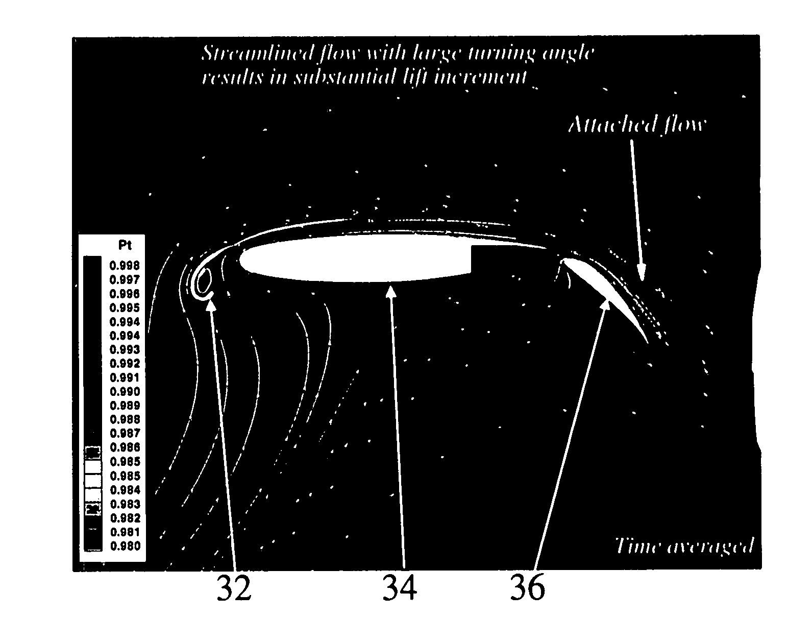
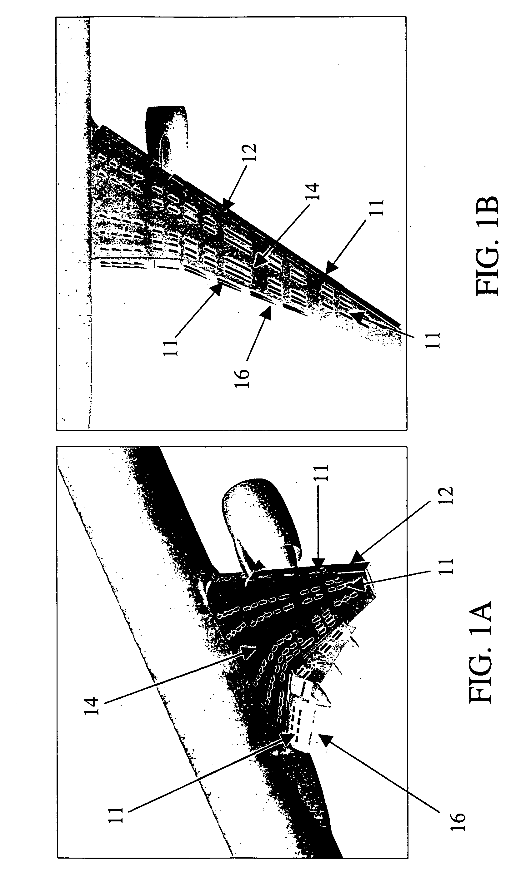
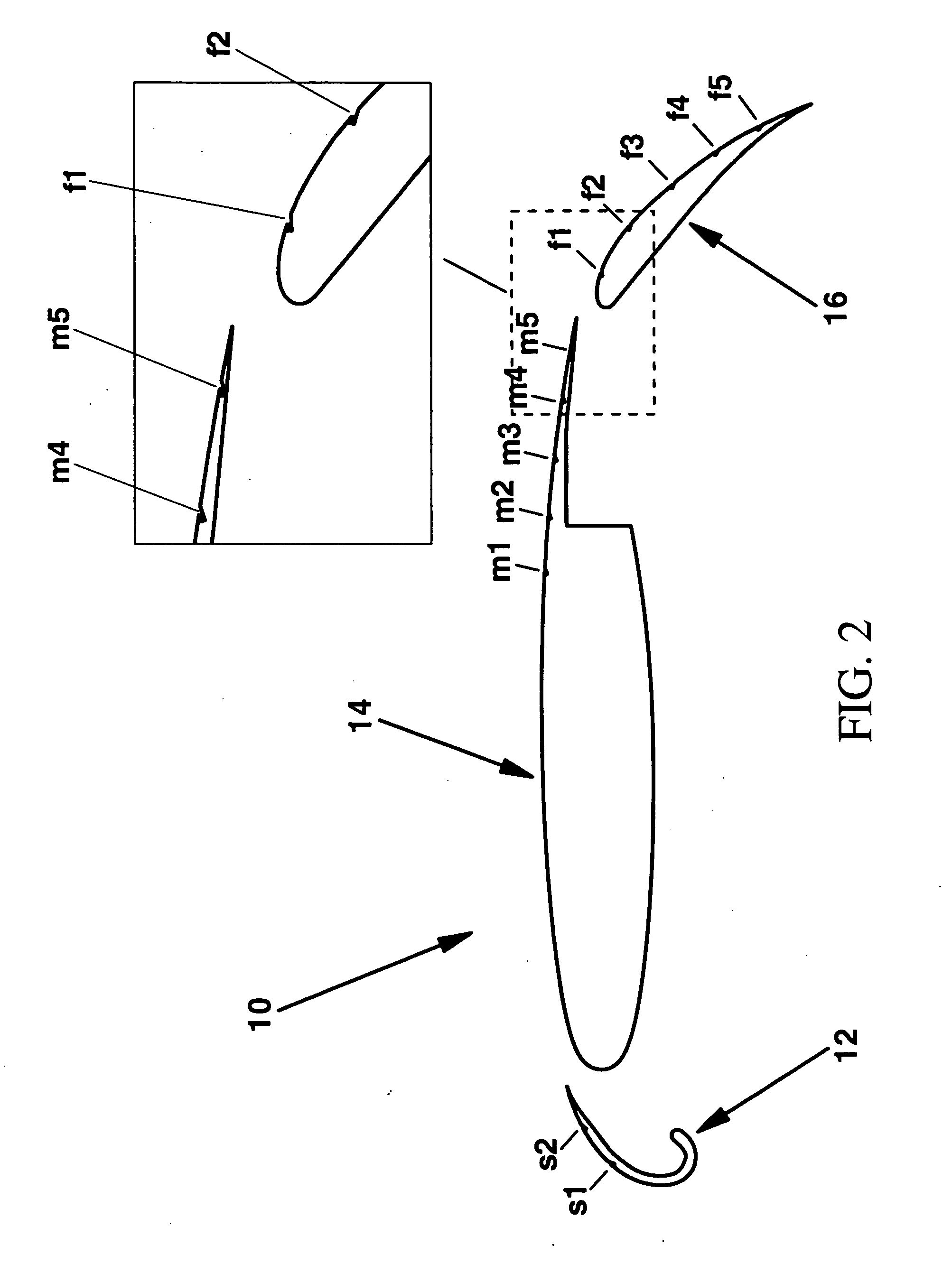
[0035] Referring now to the drawings and, in particular to FIGS. 1A-B, there is shown a system for increasing lift of a multi-element aircraft wing 10. The aircraft wing 10 generally includes a plurality of wing elements 12, 14, and 16. Each of the wing elements 12, 14, and 16 includes a plurality of ports 11 defined therein. Fluidic devices (not shown) are utilized to regulate the flow of fluid into and out of the ports 11 to control boundary layer flow over each of the wing elements 12, 14, and 16. Generally, ...


PUM


Abstract

A system and method for generating lift provided by a multi-element aircraft wing are provided. The system includes a main wing element, a slat interconnected to the main wing element, and a flap interconnected to the main wing element. The system also includes at least one port defined in at least one of the slat, main wing element, and flap. In addition, the system includes at least one fluidic device operable to regulate fluid flow into and out of the at least one port to control boundary layer flow over at least one of the slat, main wing element, and flap.

Description

BACKGROUND OF THE INVENTION [0001] 1) Field of the Invention [0002] The present invention relates to aircraft wings and, more particularly, to a lift augmentation system for increasing lift of a multi-element aircraft wing by controlling boundary layer flow over the aircraft wing. [0003] 2) Description of Related Art [0004] Takeoff and landing performance are two principal design objectives for transport aircraft. Any aircraft design is limited to a maximum takeoff weight which is related to the runway length. For a given runway length, higher lift levels permits the maximum take-off weight to be increased. Equivalently, for a given weight, higher lift allows for lower stall speed and shorter runway length. From an operational perspective, high-lift capability results in access to a larger number of airports. Whether the requirement is for a larger payload or for shorter runways, superior high-lift capability is a key objective of the aircraft manufacturers. [0005] For a given aircr...

Claims


Application Information

Patent Timeline
Patent Type & Authority Applications(United States)
IPC IPC(8): B64C21/04
CPCB64C9/16B64C9/22B64C21/025Y02T50/166B64C2230/18Y02T50/44B64C2230/06B64C2230/04Y02T50/32Y02T50/10Y02T50/30Y02T50/40
Inventor SHMILOVICH, ARVINYADLIN, YORAMCLARK, ROGER W.
Owner THE BOEING CO
Why Eureka
Try Eureka