

Flare-shaped end structure for tube
- Summary
- Abstract
- Description
- Claims
- Application Information
AI Technical Summary
Benefits of technology
Problems solved by technology
Method used
Image

Examples
Embodiment Construction
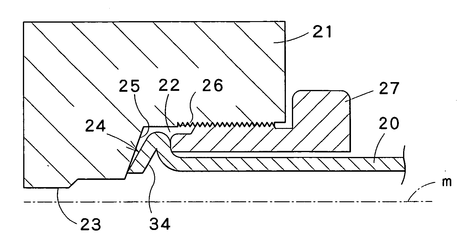
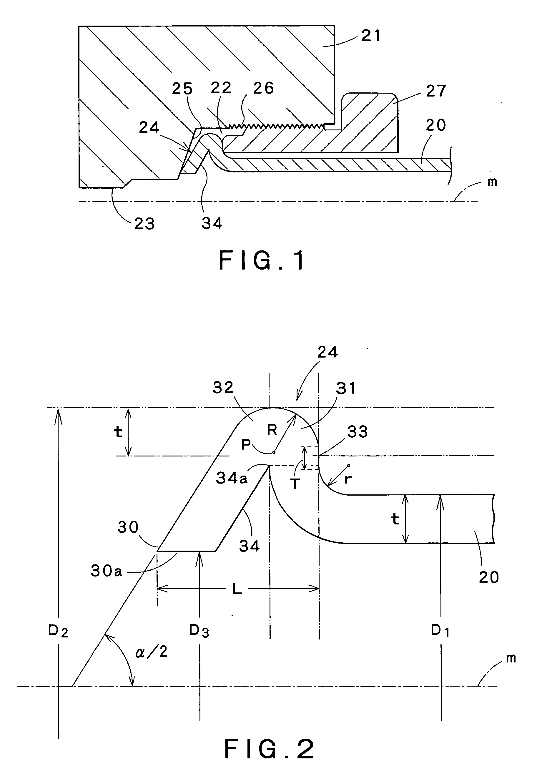
[0033]FIG. 1 is a longitudinal half sectional view of a flared type pipe joint for connecting a tube having a flared end structure in a first embodiment according to the present invention to a port of a hydraulic cylinder. In FIG. 1, indicated at 20 is a metal tube provided with a flared end structure 24 in the first embodiment and at 21 is the body of the hydraulic cylinder. The body 21 is provided with an inlet port 22 connected to an oil passage 23. A tapered seat 25 is formed at the bottom of the inlet port 22. A coupling nut provided with an external thread is slidably put on the tube 20. The inlet port 22 is provided with an internal thread 26. The coupling nut 27 is screwed in the inlet port 22. The coupling nut 27 is tightened to press the flared end structure 24 of the tube 20 against the seat 25 of the body 21. The flared end structure 24 is formed by expanding an end part of the tube 20 in a substantially conical shape. The flared end structure 24 has dimensions and featu...
PUM
| Property | Measurement | Unit |
|---|---|---|
| Diameter | aaaaa | aaaaa |
| Thickness | aaaaa | aaaaa |
| Pressure | aaaaa | aaaaa |
Abstract
Description
Claims
Application Information