

Liquid crystal display and method of controlling the same
- Summary
- Abstract
- Description
- Claims
- Application Information
AI Technical Summary
Benefits of technology
Problems solved by technology
Method used
Image

Examples
first embodiment
[0046] An exemplary LCD according to the present invention will be described with reference to the FIGS. 1 through 3.
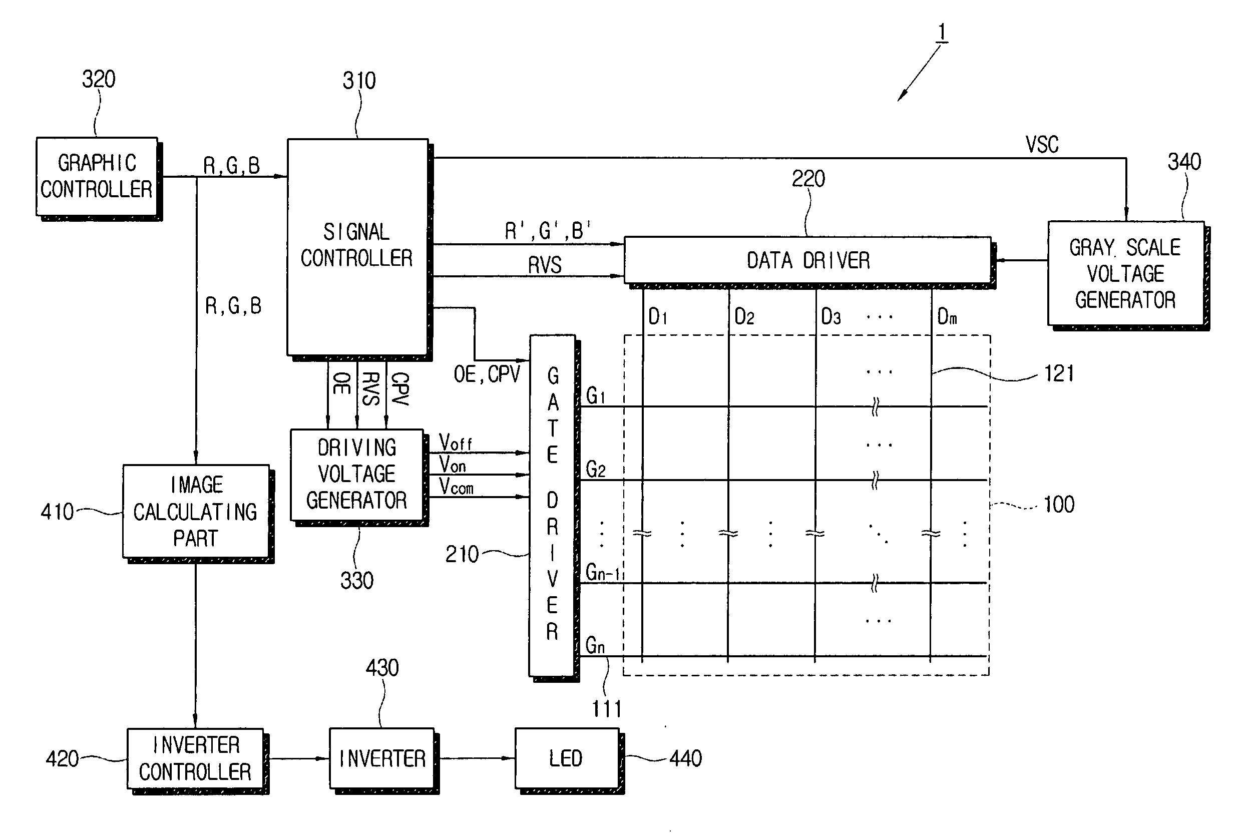
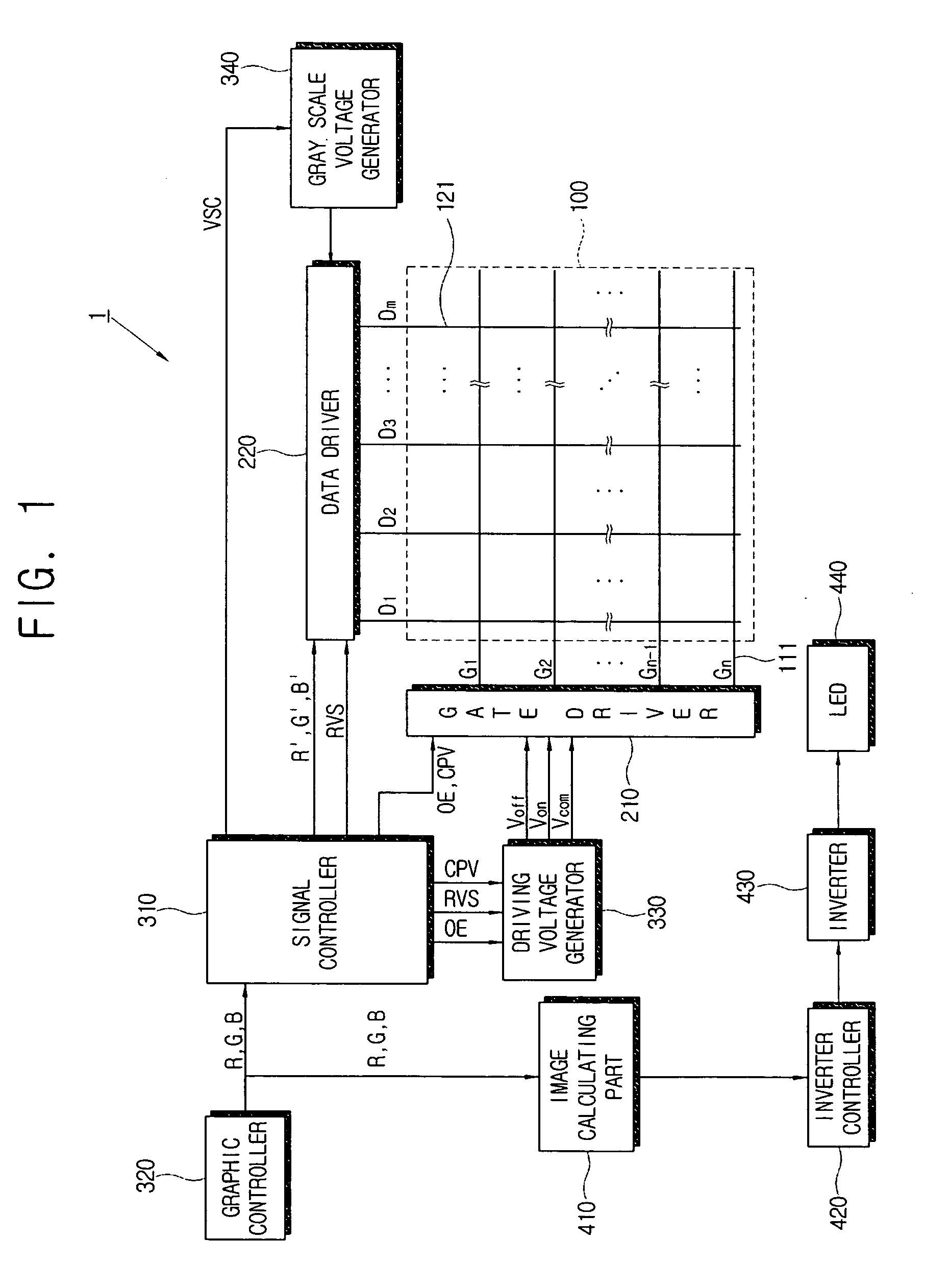
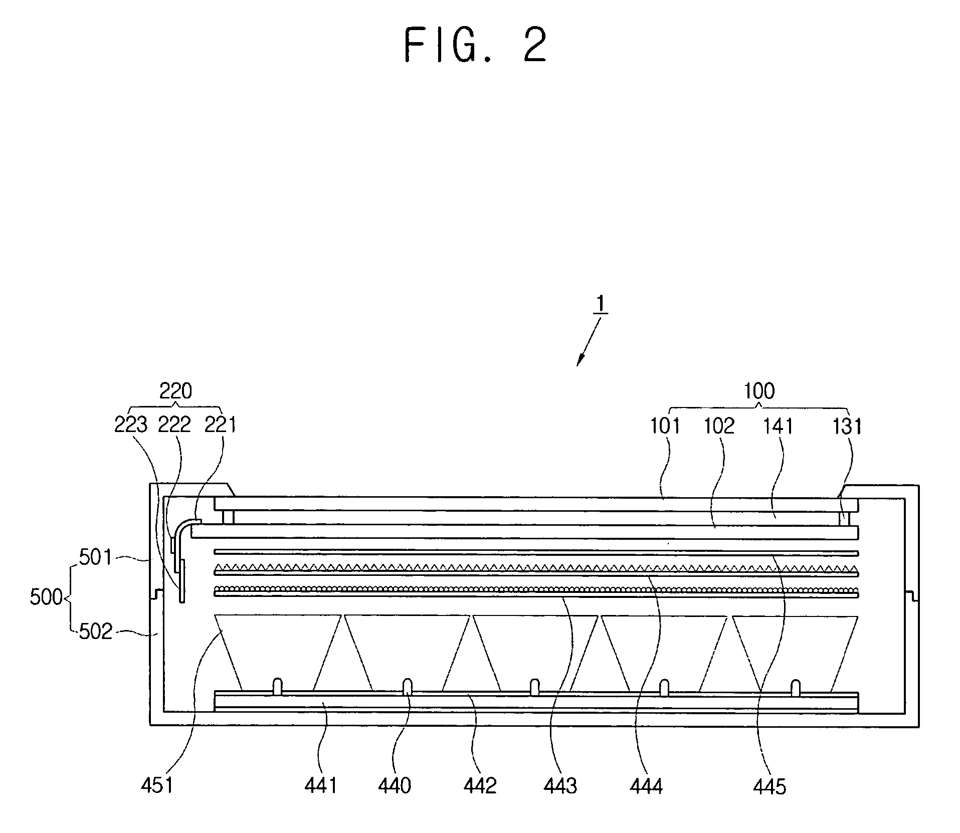
[0047]FIG. 1 is a block diagram of an LCD according to the first embodiment of the present invention, and FIG. 2 is a sectional view of the LCD according to the first embodiment of the present invention. FIG. 3 is a view for illustrating an arrangement of an LED and a light guide part according to the first embodiment of the present invention.
[0048] An LCD 1 of embodiments of the present invention comprises an LCD panel 100, a gate driver 210 and a data driver 220 connected to the LCD panel 100, a driving voltage generator 330 connected to the gate driver 210 and a gray scale voltage generator 340 connected to the data driver 220, and a signal controller 310 which controls the above components and receives image data from a graphic controller 320. The image data from the graphic controller 320 is also provided to an image calculating part 410. The image calculating p...
second embodiment
[0084]FIG. 7 is a drawing for illustrating an exemplary arrangement between an LED and a light guide part according to the present invention.
[0085] The light guide part according to the second embodiment of the present invention comprises a transparent pillar 452 substantially the same as the pillars 451 of the first embodiment. However, a section of the transparent pillar 452 is a hexagon shape. The light emitted from the LED 440 exits the LED 440 in a circular shape. Accordingly, the transparent pillar 452 is a hexagonal pillar which is more similar to the circular shape and is filled with more planes and thus, the light efficiency can be increased.
[0086]FIG. 8 is a perspective view for illustrating an exemplary arrangement between an LED and a light guide part according to a third embodiment of the present invention. FIG. 9 is a drawing for illustrating a light path in the LCD according to the third embodiment of the present invention.
third embodiment
[0087] In the present invention, a partition 453 is provided as the light guide part. The partition 453 is higher than the LEDs 440. A part surrounded by the partition 453 is referred to as a partitioned area. A plurality of the LEDs 440 are provided in each partitioned area. The LEDs 440 having different colors are disposed in each partitioned area so that white light is provided in it by mixing colors.
[0088] As shown in FIG. 9, the light generated from the LEDs 440 is directed to the LCD panel 100 or is reflected by the partition 453 and is then directed to the LCD panel 100. Accordingly, the light from the LEDs 440 has less influence on the brightness of another adjacent partitioned area by the partition 453. In addition, an efficiency of the color mixing can be increased due to a light reflection of the partition 453. The partition 453 can be formed with a white color film having good reflectivity and can comprise polyethylene terephthalate (PET), polycarbonate (PC), and the lik...
PUM
 Abstract
Description
Claims
Application Information