
Tuning circuit for preventing a deterioration of Q value

a tuning circuit and q value technology, applied in the field of tuning circuits, can solve the problems of easy deterioration of achieve the effect of preventing the widening of bandwidth and improving rf characteristic of tuning circuits

Inactive Publication Date: 2007-03-08
ALPS ALPINE CO LTD
View PDF6 Cites 6 Cited by
  • Summary
  • Abstract
  • Description
  • Claims
  • Application Information

AI Technical Summary

Benefits of technology

[0011] The present invention has been proposed to solve the above problems, and it is an object of the present invention to provide a tuning circuit for improving an RF characteristic by preventing a deterioration of a Q value.
[0021] Accordingly, since the tuning circuit can be formed with a simple structure, the reduction in manufacturing cost and the miniaturization of the circuit are achieved.
[0023] Accordingly, a potential of the anode of the second variable capacitor diode can be adjusted at plural steps. Thus, setting of the resonance circuit frequency can be more finely adjusted.
[0026] In the invention, the reduction of the Q value is prevented by the ON-resistor of the switch element.
[0027] Further, since the wideness of the bandwidth can be prevented, the RF characteristic of the tuning circuit is possibly improved.

Problems solved by technology

Further, since the ON-resistance is large when the switch diode is ON, the bandwidth BW is widened by the reduction of the value of Q. As a result, there has been a problem that an RF characteristic of the tuning circuit is easily deteriorated as the tuning frequency is increased.

Method used


Image

  • Tuning circuit for preventing a deterioration of Q value
  • Tuning circuit for preventing a deterioration of Q value
  • Tuning circuit for preventing a deterioration of Q value

Examples


first embodiment

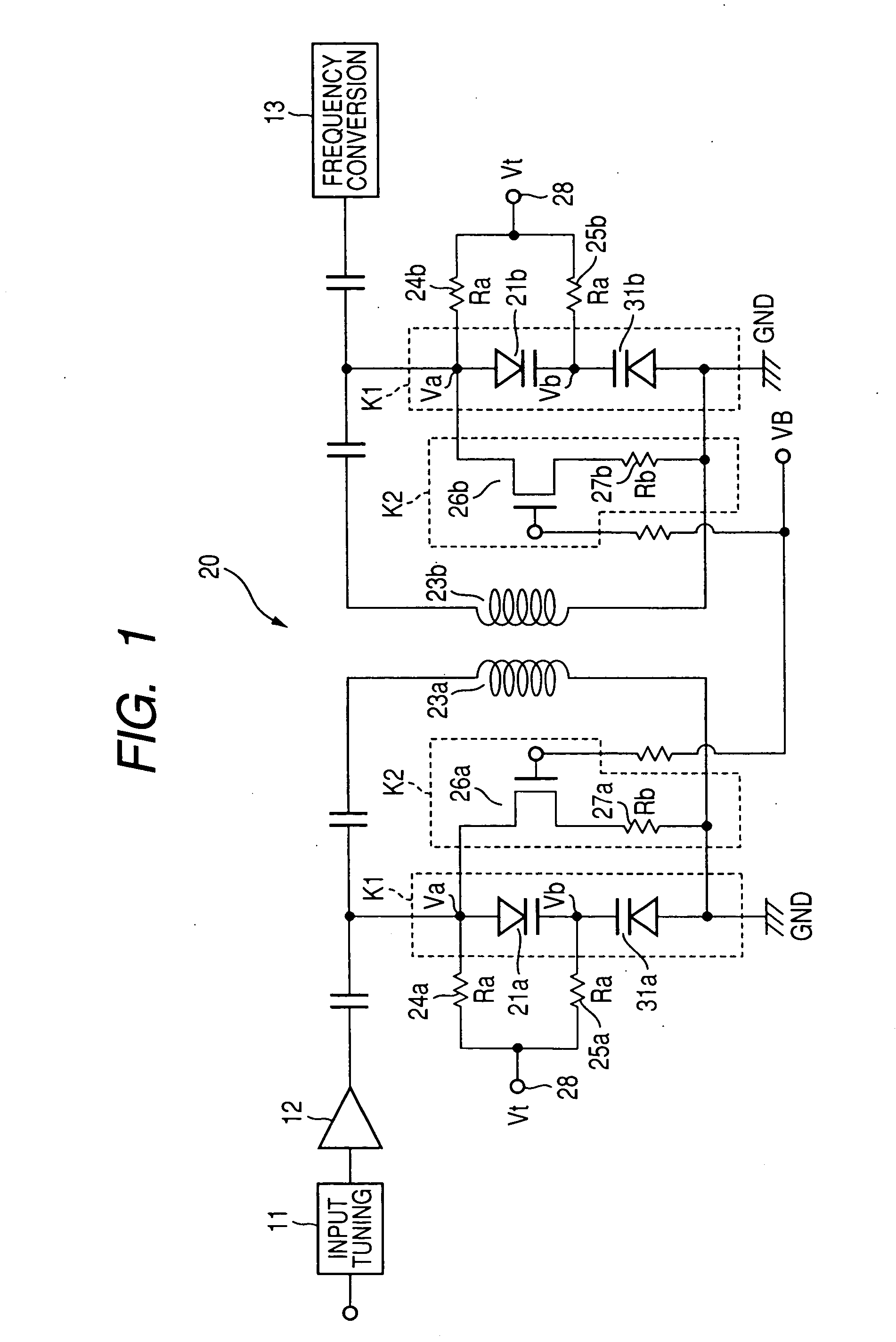
[0031]FIG. 1 is a circuit diagram schematically showing a television tuner having a tuning circuit of the present invention.

[0032] As shown in FIG. 1, the television tuner includes a band switching-type input tuning circuit 11 which is adapted to tune to a low band or a high band of VHF band and a high frequency amplifying circuit 12 provided at the next stage of the band switching-type input tuning circuit 11. Further, an interstage tuning circuit 20, which is the tuning circuit of the invention, is provided at the next stage of the high frequency amplifying circuit 12, and a frequency conversion circuit 13 consisting of a mixing circuit is provided at the rear stage of the interstage tuning circuit 20. Moreover, direct current cutting capacitors are provided between the high frequency amplifying circuit 12 and the interstage tuning circuit 20, and between the interstage tuning circuit 20 and the frequency conversion circuit 1.

[0033] The interstage tuning circuit 20 is constituted...

second embodiment

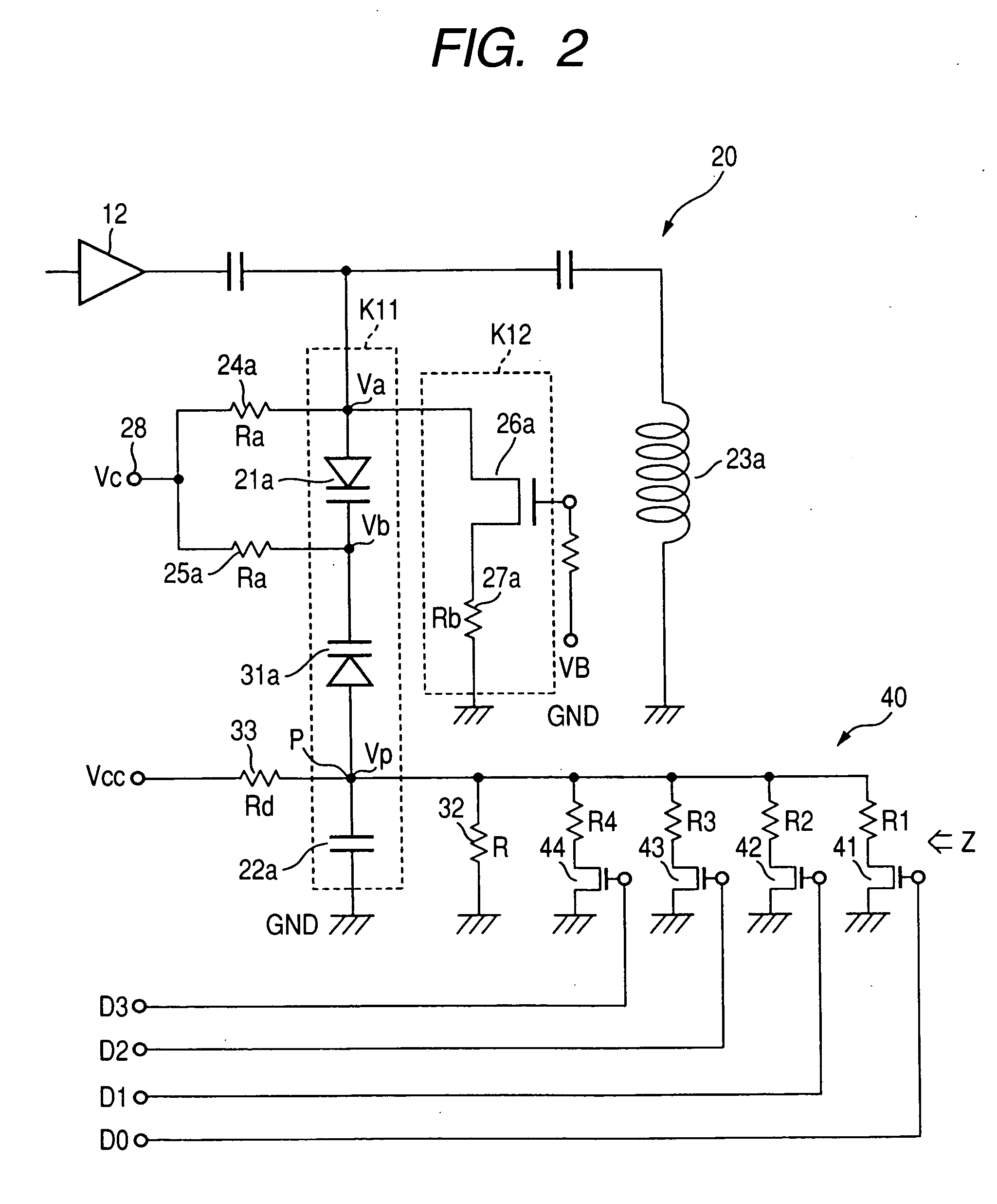
[0058] As shown in FIG. 2, a tuning circuit 20B as a second embodiment includes a first circuit K11 in which a first variable capacitor element 21a subsequently lined up from a non-grand side to a grand side, a second variable capacitor element 31a and a capacitor 22a are serially connected. Also in this embodiment, the first variable capacitor element 21a and the second variable capacitor element 31a are all formed with the variable capacitor diode, and the cathodes of both ends thereof are connected to each other. The resonance circuit is formed by the first circuit K11 and the inductance element 23a which are parallely connected to each other.

[0059] The switch element 26a and the third resistor 27a with a resistance value Rb is serially connected, and the second circuit D12 is parallely connected to the first circuit K11 consisting of the first variable capacitor element 21a, the second variable capacitor element 31a and the capacitor 22a.

[0060] The first resistor 24a is connect...


PUM


Abstract

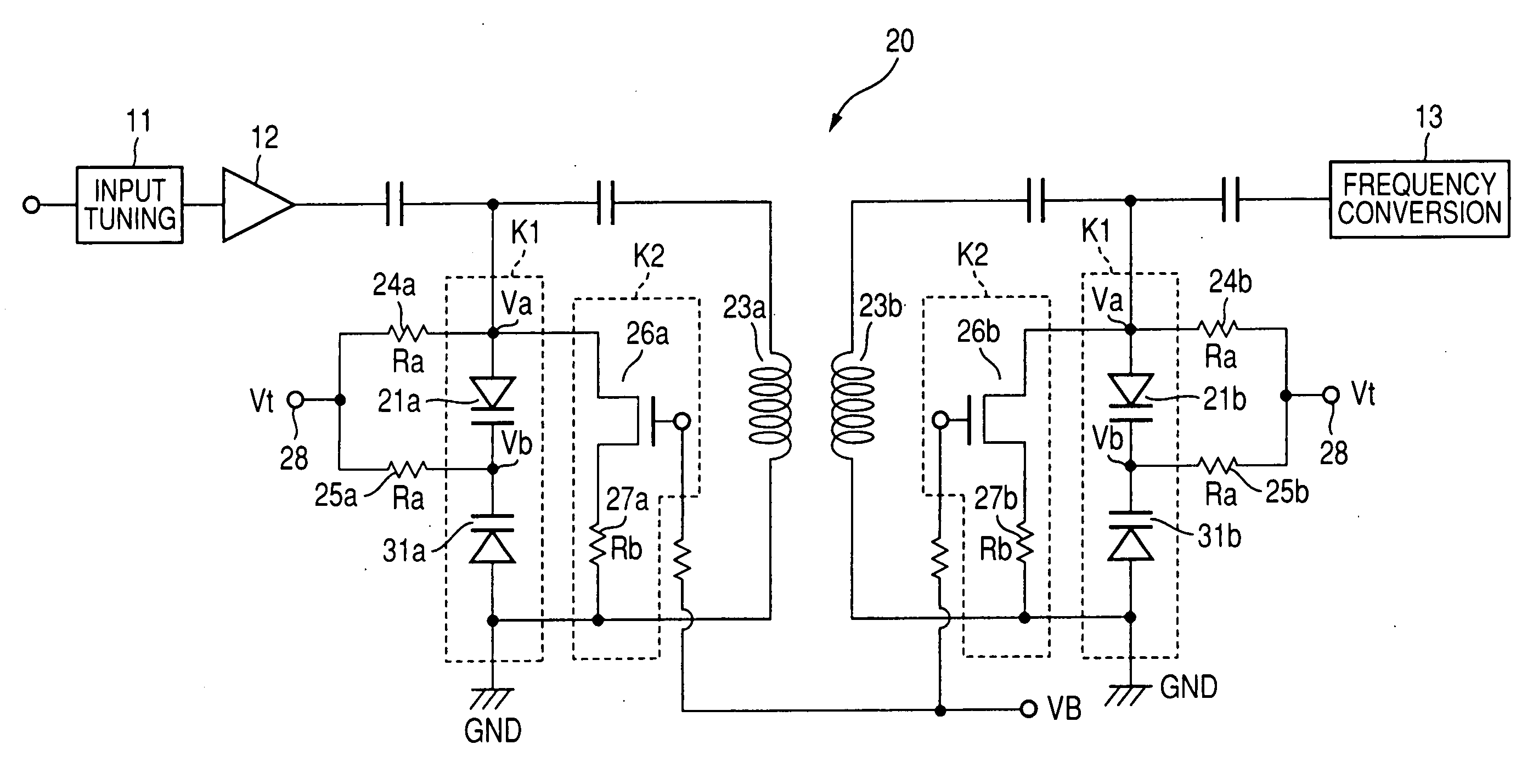
A tuning circuit comprises, at least, a first circuit K1 which serially connects a first variable capacitor element 21a and a second variable capacitor element 31a, an inductance element 23a which is parallely connected to the first circuit K1 and constitutes a resonance circuit with the first circuit K1; a second circuit K2 which includes a switch element 26a and a third resistor 27a serially connected to each other and is parallely connected to the first circuit K1; and a first resistor 24a and a second resistor and 25a which are connected to both ends of the first variable capacitor element 21a, respectively and apply a predetermined tuning voltage.

Description

FIELD OF THE INVENTION [0001] The present invention relates to a tuning circuit installed in a television tuner, and more particularly to a tuning circuit which can prevent a deterioration of Q value and improve an RF characteristic. DESCRIPTION OF THE RELATED ART [0002] As a prior art of the present invention, there is exemplified JP-A-2003-309777 described below. [0003] As shown in JP-A-2003-309777, a conventional television tuner comprises a band switching-type input tuning circuit 1 which is adapted to tuned to a low band or a high band of VHF band, a high frequency amplifying circuit 2 and an interstage tuning circuit 3. [0004] The interstage tuning circuit 3 is constructed by a double tuning circuit, and includes a (parallel) resonance circuit whose primary and secondary portions comprise inductance elements 3a and 3c, and capacitors and varactor diodes 3b and 3d, respectively. A part of each of the inductance elements 3a and 3c is short-circuited by switch means 3e and 3f for...

Claims


Application Information

Patent Timeline
IPC IPC(8): H03B5/08H04N5/50H03J3/32H04N5/44
CPCH03J3/08H03J5/0218H03J3/26H03J3/20
Inventor SUZUKI, TAKEOOSADA, SHIGERU
Owner ALPS ALPINE CO LTD
Learn More