
Image processing apparatus for reading compressed data from and writing to memory via data bus and image processing method

a data bus and image processing technology, applied in the field of image processing apparatus, can solve the problems of image quality deterioration, other units will be unable to process, memory bus breakdown, etc., and achieve the effect of preventing the breakdown of memory bus bandwidth and preventing the deterioration of image quality

Inactive Publication Date: 2008-11-27
RENESAS ELECTRONICS CORP
View PDF7 Cites 7 Cited by
  • Summary
  • Abstract
  • Description
  • Claims
  • Application Information

AI Technical Summary

Benefits of technology

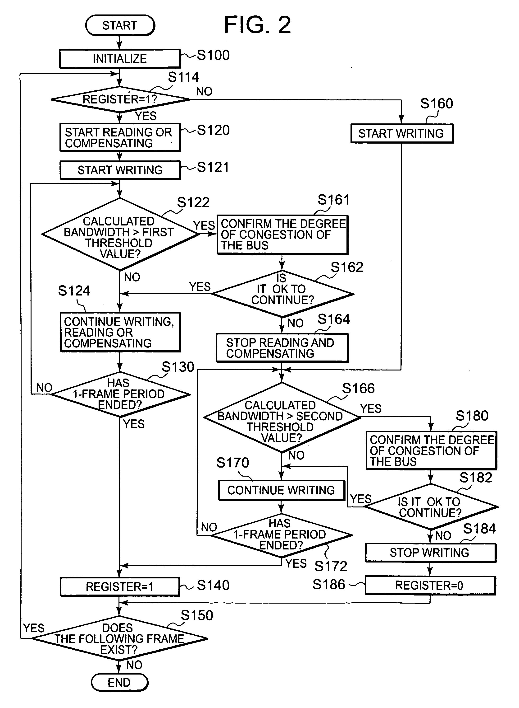
[0020]According to the art related with this invention, it is possible to prevent the breakdown of memory bus bandwidth and prevent the deterioration of the image quality while the current frame image is compressed and the compressed data is stored in the shared memory, and compressed data of the adjacent frame image stored in the shared memory is read out and decompressed.

Problems solved by technology

This is because, if a processing unit uses excessively the memory bus bandwidth, there develops a problem of memory bus breakdown in that other units will be unable to process.
The art disclosed in Patent Document 4 has a problem in that it can reduce the memory used by the compression procession unit and consequently the memory bus bandwidth by raising the compression ratio but that the image quality deteriorates when the compression ratio is reduced.
There is a compression algorithm with variable amount of compressed data even with the same compression ratio, for example reversible compression, and in the case of compression with such a compression algorithm, it is necessary to allocate the amount of memory used to each block by assuming in advance the maximum amount of compressed data, and therefore waste can result.
For example, even when other processing units use less bus bandwidth than calculated, the bus bandwidth opened by the image coder / decoder unit cannot be used, and as a result efficiency is low.

Method used


Image

  • Image processing apparatus for reading compressed data from and writing to memory via data bus and image processing method
  • Image processing apparatus for reading compressed data from and writing to memory via data bus and image processing method
  • Image processing apparatus for reading compressed data from and writing to memory via data bus and image processing method

Examples


Embodiment Construction

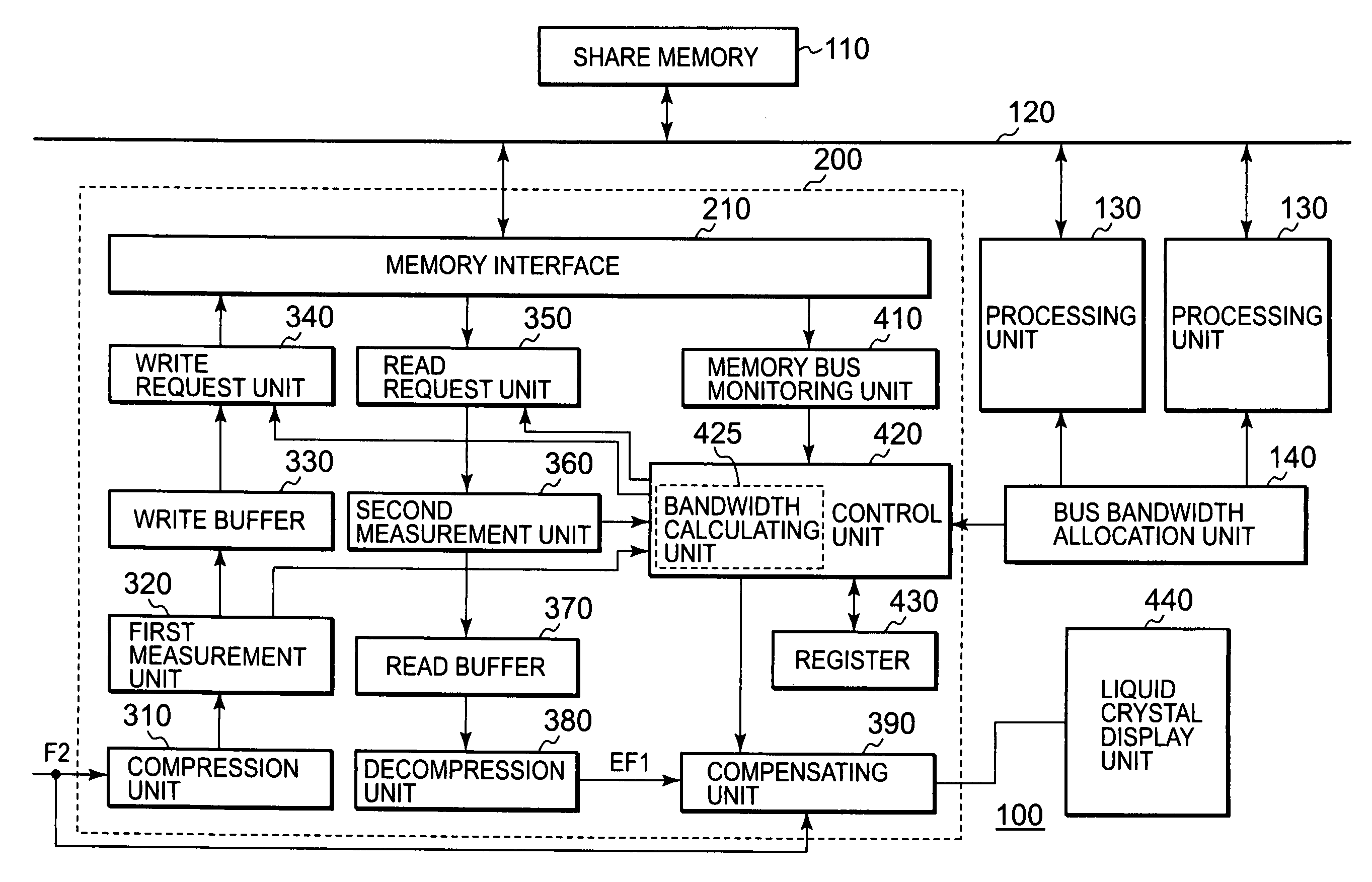
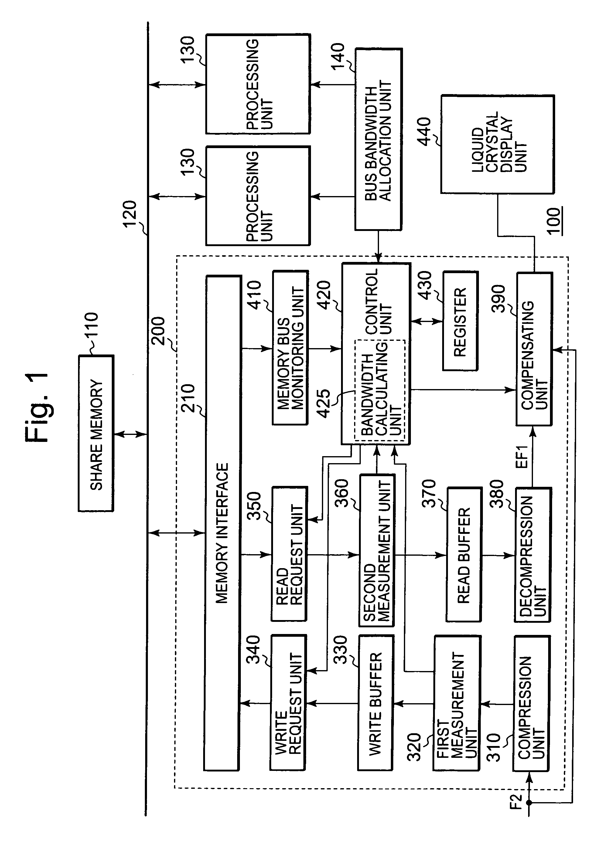
[0029]FIG. 1 shows an image processing apparatus 100 related to the mode of carrying out this invention. The image processing apparatus 100 includes a shared memory 110, a memory bus 120, a plurality of processing units 130, a bus bandwidth allocation unit 140, an overdrive processing unit 200, and a liquid crystal display unit 440.

[0030]The overdrive processing unit 200 and the processing unit 130 access the shared memory 110 through the memory bus 120.

[0031]The bus bandwidth allocation unit 140 allocates respectively, for example at the time of initializing the image processing apparatus 100, a predetermined amount of the bandwidth of the memory bus 120 used by a plurality of processing units 130 and the overdrive processing unit 200. As long as the plurality of processing units 130 and the overdrive processing unit 200 access the shared memory 110 within the limit of the memory bus bandwidth allocated to themselves, the respective bandwidth is determined in such a way that no bre...


PUM


Abstract

An image processing apparatus includes a data bus provided to access a memory, a compressing unit which compresses an image data and outputs a compressed image data, a write unit which writes the compressed image data into the memory via the data bus, a read unit which reads a compressed image from the memory via the data bus, a decompression unit which decompresses the compressed data read by the read unit, and a control unit which controls operations of the write unit and the read unit, based on an amount per unit time of the compressed image data outputted from the compressing unit, an amount per unit time of the compressed image data read from the memory and a degree of congestion of the data bus.

Description

BACKGROUND OF THE INVENTION[0001]1. Field of the Invention[0002]This invention relates to an image processing art, specifically to the control for compressing the current frame image and storing the compressed data in a shared memory and for reading and decompressing the compressed data of the adjacent frame image stored in the shared memory.[0003]2. Description of Related Art[0004]A variety of methods are proposed to decrease the use of memory and to prevent the posterior processing unit from overflowing at the time of compressing and decompressing image data.[0005]For example, Patent Document 1 discloses the art of compressing image data according to the compression conversion rule corresponding to image data luminance information as a technology of reducing the use of memory and storing the compressed data and the compression conversion rule in the memory. At the time of decompression, the compressed data and the compression conversion rule are read from the memory, and the compr...

Claims


Application Information

Patent Timeline
IPC IPC(8): G06F13/00G09G3/20G09G3/36G09G5/00H04N19/00H04N19/102H04N19/134H04N19/196H04N19/423H04N19/426
CPCH04N19/42H04N19/00G09G3/36G09G5/39
Inventor FUJI, KAZUHIRO
Owner RENESAS ELECTRONICS CORP
Learn More