Receiver circuit and a method for its operation

a receiver circuit and receiver technology, applied in the field of receiver circuits, can solve the problems of high noise level of amplifier devices, and achieve the effect of reducing noise and producing the receiver circuit as simple and cost-effectively

Inactive Publication Date: 2009-01-27
INFINEON TECH AG
View PDF13 Cites 6 Cited by
  • Summary
  • Abstract
  • Description
  • Claims
  • Application Information

AI Technical Summary

Benefits of technology

[0004]The invention provides a receiver circuit which has minimal noise. The invention also provides a method for producing the receiver circuit as simply and cost-effectively as possible, and preferably to operate digitally, or very largely digitally.
[0005]According to the invention, a receiver circuit includes at least one amplifier device for amplification of a data signal which is applied to the input side of the receiver circuit. The receiver circuit also has a control device, which measures the data rate of the data signal and sets the bandwidth of the amplifier device such that the bandwidth of the amplifier device corresponds to the data rate of the data signal. The control device thus results in the amplifier device always operating with a bandwidth which corresponds optimally to the respective data signal; this therefore avoids the amplifier device having a bandwidth which is excessively great or is too large.
[0013]Furthermore, it is regarded as being advantageous for the control device to have a bandwidth monitoring device which is arranged downstream from the data correlator and uses the correlation signals from the data correlator to produce a data rate measurement signal for driving the amplifier device.
[0025]Matching the bandwidth of the amplifier device to the respective data rate of the data signal allows an optimum receiver circuit noise response to be achieved—as already explained above.

Problems solved by technology

Specifically, if the bandwidth is very wide, the noise level of the amplifier device is generally also very high.

Method used


Image

  • Receiver circuit and a method for its operation
  • Receiver circuit and a method for its operation
  • Receiver circuit and a method for its operation

Examples


Embodiment Construction

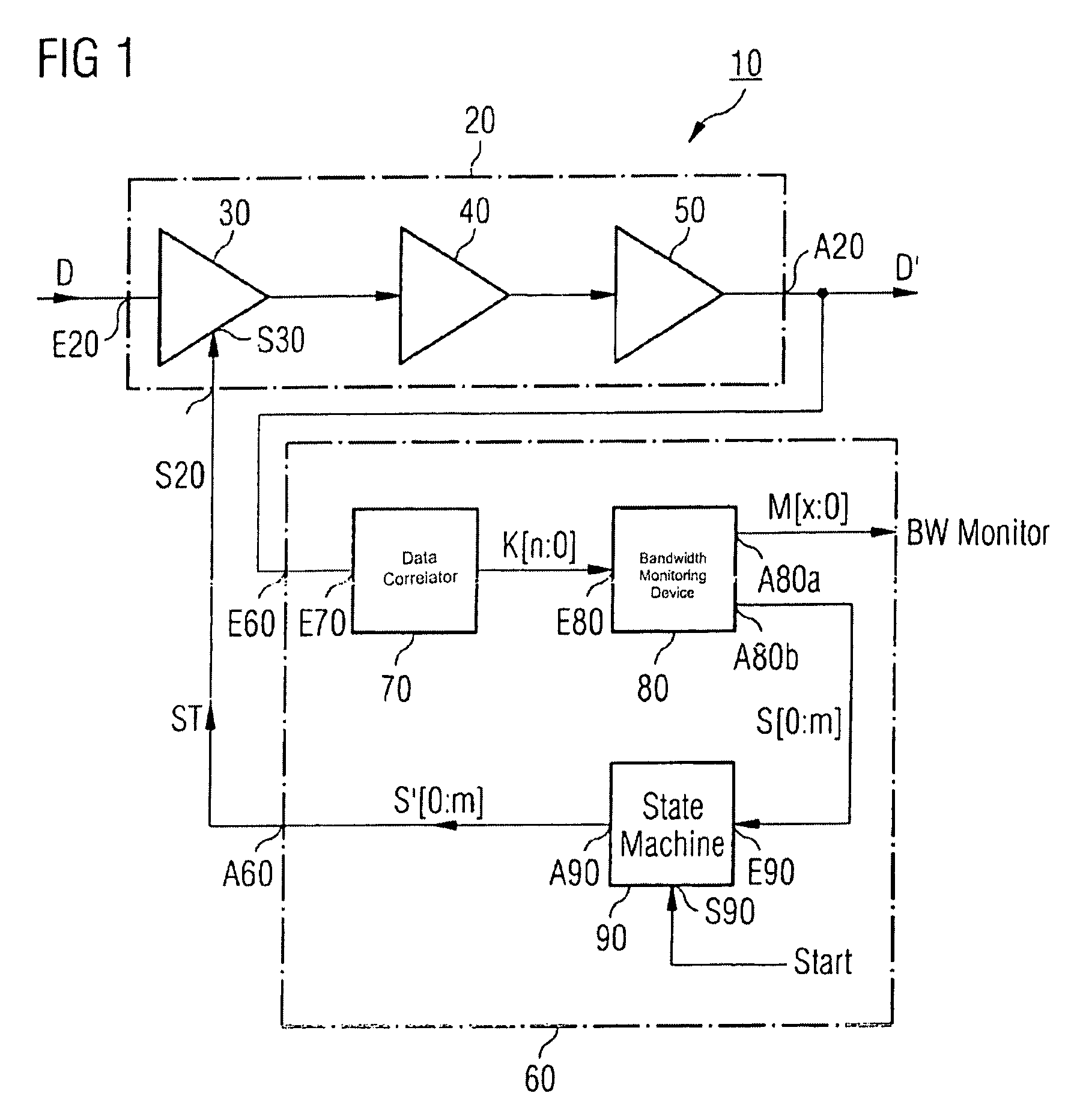
[0034]FIG. 1 shows a receiver circuit 10 which, for example, forms a component of an optical receiving element. This means that the receiver circuit is suitable for processing a measurement signal from an optoelectronic transducer.

[0035]On the input side, the receiver circuit 10 has an amplifier device 20, at whose input E20 a data signal D is fed into the receiver circuit 10. The data signal D is, for example, formed by an optoelectronic transducer, which is not illustrated in FIG. 1, of an optical receiving element.

[0036]The amplifier device 20 has three amplifiers 30, 40 and 50 which are connected in series and thus form an amplifier chain. The first amplifier 30, as seen from the input side, is an amplifier which can be driven via a control input S30. The bandwidth and hence the noise response of the amplifier 30 can be fixed by presetting a control signal ST at the control input S30.

[0037]The bandwidth and thus the noise response of the amplifier 30 may, for example, be varied ...


PUM


Abstract

A receiver circuit having at least one amplifier device for amplification of a data signal which is applied to the input side of the receiver circuit, and having a control device which measures the data rate of the data signal and sets the bandwidth of the amplifier device such that the bandwidth of the amplifier device corresponds to the data rate of the data signal.

Description

RELATED APPLICATION[0001]The present application claims priority of U.S. patent application Ser. No. 60 / 540,759 filed by Karl Schrodinger on Jan. 30, 2004.FIELD OF THE INVENTION[0002]The invention relates to a receiver circuit and to a method for operation of a receiver circuit.BACKGROUND OF THE INVENTION[0003]Receiver circuits are used, for example, in optical information technology in order to amplify the electrical measurement signal which is supplied from an optoelectronic transducer, and then to process this measurement signal further.SUMMARY OF THE INVENTION[0004]The invention provides a receiver circuit which has minimal noise. The invention also provides a method for producing the receiver circuit as simply and cost-effectively as possible, and preferably to operate digitally, or very largely digitally.[0005]According to the invention, a receiver circuit includes at least one amplifier device for amplification of a data signal which is applied to the input side of the receiv...

Claims


Application Information

Patent Timeline
Patent Type & Authority Patents(United States)
IPC IPC(8): H04B1/66H04B1/00H03K5/08H04B10/158H04L25/02H04L25/45H04L27/06
CPCH03G3/3052H03G3/3089H03G5/005H03K5/086H04B10/66H04L25/0262H04L25/45
Inventor SCHRODINGER, KARL
Owner INFINEON TECH AG
Why Eureka
Try Eureka