Substrate film for optical sheet, optical sheet and backlight unit

a technology of substrate film and backlight unit, which is applied in the field of substrate film for an optical sheet, optical sheet, and backlight unit, can solve the problems of insatiable current circumstances of a cold-cathode tube such as a cold-cathode tube, and improve the optical waveguide plate b>52/b> and the lamp b>51/b> in the backlight unit b>50/b>, so as to facilitate high-luminance-

Active Publication Date: 2007-03-08
KEIWA INCORPORATED
View PDF20 Cites 19 Cited by
  • Summary
  • Abstract
  • Description
  • Claims
  • Application Information

AI Technical Summary

Benefits of technology

[0025] The optical sheet of the present invention which was made for solving the problem as described above has the substrate film for an optical sheet, and an optical layer overlaid on one face of this substrate film for the optical sheet. The optical sheet can actively convert the polarization orientation of the rays of light outgoing from the optical waveguide plate or the like into the transmission axial orientation of the polarizing plate or the like by means of the substrate film for the optical sheet. Therefore, when the optical sheet is used in, for example, a liquid crystal display device, utilization efficiency of the rays of light can be markedly enhanced, and thus, high-luminance and energy-saving modeling can be facilitated.
[0026] The optical layer may include multiple particles of a light diffusing agent, and a binder therefor. The optical sheet is a light diffusion sheet, generally referred to, has a function to diffuse transmitted rays of light by the multiple transmitted rays of lights included in the optical layer, and can facilitate the high-luminance and energy-saving modeling by means of the substrate film for the optical sheet.
[0027] Moreover, the aforementioned optical layer may also have a microlens array constructed with multiple microlenses. The optical sheet is a microlens sheet, generally referred to, has optical functions such as high light condensation of the transmitted rays of light, and refraction and diffusion to the normal line orientation and the like by means of the microlens array. Accordingly, high-luminance and energy-saving modeling can be facilitated by means of the substrate film for the optical sheet.
[0028] A sticking preventive layer i...

Problems solved by technology

However, in order to secure the luminance while keeping the concept of LCD, i.e., thin and light modeling, merely improving the optic...

Method used


Image

  • Substrate film for optical sheet, optical sheet and backlight unit
  • Substrate film for optical sheet, optical sheet and backlight unit
  • Substrate film for optical sheet, optical sheet and backlight unit

Examples


examples

[0135] Hereinafter, the present invention will be explained in detail by way of Examples, however, the present invention should not be construed as being limited to the description of these Examples.

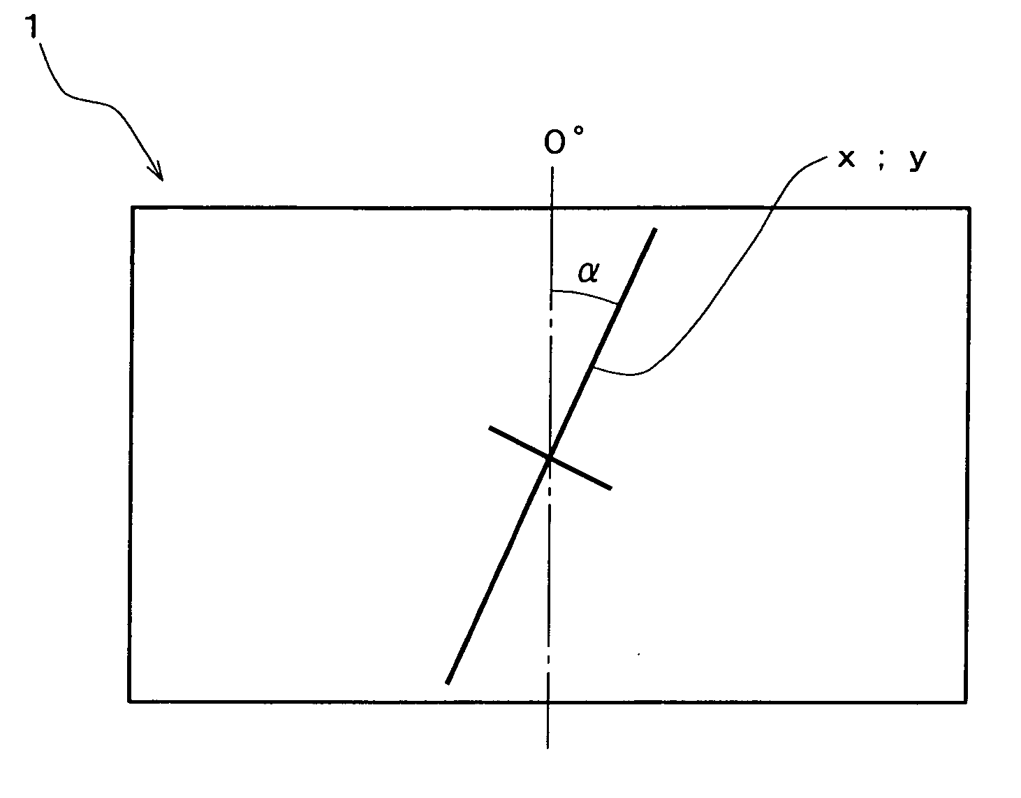
[0136] Relationship between Angle a in Crystal Orientation with respect to Short Side Orientation and Front Luminance

[0137] Light diffusion sheets were produced by: sampling at different positions from an original film obtained through biaxially stretching polyethylene terephthalate; producing rectangular substrate films for an optical sheet having a variety of angles of the crystal orientation with respect to the short side orientation; and laminating a similar light diffusion layer thereon.

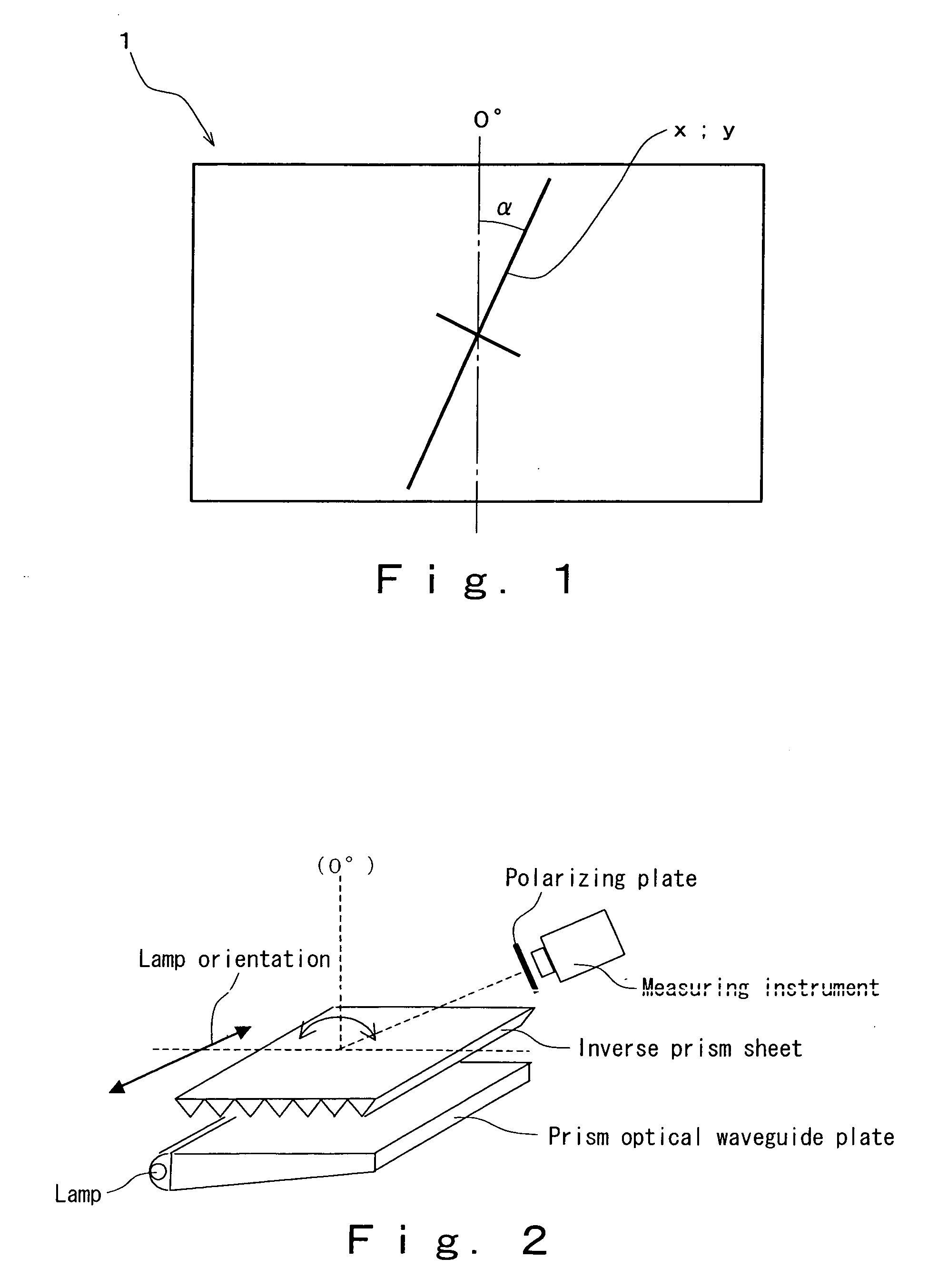
[0138] Front luminance was measured when these light diffusion sheets were incorporated in a liquid crystal module having a transmission axis of the polarizing plate of the liquid crystal cell being 45° with respect to the lamp orientation. Relationship between the crystallographic axial angle α a...


PUM


Abstract

Disclosed is a substrate film for an optical sheet, an optical sheet and a backlight unit capable of markedly enhancing utilization efficiency of rays of light and improving luminance. The substrate film for an optical sheet is made of a transparent resin and is formed into a rectangular shape, which substrate film for the optical sheet has an optical anisotropy, and having an absolute value of the angle of the crystal orientation with respect to the short side orientation being π/16 or greater and 3π/16 or less. The crystal orientation preferably follows the phase advancing axial orientation. The substrate film for the optical sheet has a retardation value such that average intensity of transmitted beam IA becomes equal to or greater than 0.75 so as to be capable of converting polarization orientation of outgoing rays of light of the optical waveguide plate or the like to the transmission axial orientation of the polarizing plate or the like. The retardation value is preferably 140 nm or greater and 390 nm or less. The transparent resin is preferably polyethylene terephthalate or polycarbonate. The optical sheet has the substrate film for the optical sheet, and an optical layer.

Description

BACKGROUND OF THE INVENTION [0001] 1. Field of Invention [0002] The present invention relates to substrate films for an optical sheet, optical sheets, and backlight units capable of markedly enhancing utilization efficiency of rays of light and improving luminance. [0003] 2. Description of the Related Art [0004] Liquid crystal display (LCD) devices have been frequently used as a flat panel display through utilizing features of thinness, lightness in weight and low level of electric power consumption, and applications thereof have been increasing year by year. The liquid crystal display devices in widespread use have involved a backlight system where light emission is executed by irradiating onto a liquid crystal layer from the back face. In such a type of display devices, a backlight unit which is an edge light type, an immediate beneath type or the like is provided to an under face side of the liquid crystal layer. Such a backlight unit 50 of an edge light type is equipped with a r...

Claims


Application Information

Patent Timeline
IPC IPC(8): G02B27/00G02B3/00
CPCG02B6/0051G02B6/0053G02B6/0056G02F2202/40G02F1/13362G02F1/13363G02F2001/133607G02F1/133536G02F1/133607G02B5/02G02F1/1335G02B5/0226G02B5/0257G02B5/0268G02B6/0065
Inventor HARADA, KENICHI
Owner KEIWA INCORPORATED
Why Eureka
Try Eureka